Interferometric Measurement of Liquid Volumes

Active Publication Date: 2017-07-20
LUEDEMANN HANS CHRISTIAN
View PDF2 Cites 3 Cited by
  • Summary
  • Abstract
  • Description
  • Claims
  • Application Information

AI Technical Summary

Benefits of technology

The patent describes a technique called low-coherence interferometry that can accurately measure the topography of a liquid sample's surface and determine its volume using a computer. This technique has the advantage of high resolution.

Problems solved by technology

If this method is to be applied to assessing the errors in liquid delivery into individual wells, a weighing step is performed after each dispense operation, which renders the method very time consuming.
In this instance, the change in weight to be measured is also rather small, so that static electricity, drafts, and vibrations, for example, may introduce substantial errors to the measurement.
This method is limited by the accuracy with which typical absorbance plate readers determine sample absorbance.
However, in a large proportion of cases of practical relevance, the liquid meniscus is not planar.
If the meniscus is curved, measuring the liquid fill height at one point in the well is no longer sufficient to determine the volume of the liquid.
In the ratiometric photometry method described in U.S. Pat. No. 7,187,455 B2 the user is limited to specific liquids that have undergone extensive characterization.
In cases where a user wants to rapidly verify the level of accuracy and precision for a given experimental liquid and the liquid class parameters chosen for this specific experiment, the method described in U.S. Pat. No. 7,187,455 B2 does not provide a convenient solution.
Further, the method described in U.S. Pat. No. 7,187,455 B2 does not provide a convenient solution for a user who wants to measure the volume of liquid in a plate and then subsequently use that same liquid in an unaltered state for an experiment.
The presence of dyes in this method makes this impossible.
Due to inherent limitations in the distance resolution of ultrasound measurements, this method is suitable to detect the presence of liquid in a well, but the resolution is not high enough to measure liquid volumes with sufficient resolution for the needs of many liquid delivery applications.
For small wells, the ultrasonic wavefront suffers diffraction at the opening of the well, and depth information cannot be recovered from the reflection.
This also limits the usefulness of this method for microplates with smaller wells at higher density.
The utility of this method for routine calibration is limited because the liquid delivery device is very expensive and requires plates of a specific material.
Its resolution is limited by the inherent resolution limit of ultrasonic ranging.
Challenges that limit the utility of this method in a laboratory setting include the fact that the gas pressure in the sealed chamber also depends on the temperature.
Unless temperature is carefully controlled, it is a major error source.
Second, sealing each well of the plate to its corresponding piston is accomplished by a gasket that touches the top rim of the well, which bears the risk of contamination of the contents of the well.
Measurements of this type are notoriously difficult to calibrate.
If the optical path difference however is an odd multiple of half the wavelength, the beams will interfere destructively and the detector will see an irradiance minimum.
There is potential for confusion in the context of optical technologies used to study liquids.
While this is of great utility in the assessment of the thickness of films of liquid produced in industrial quantities, the need to use additional liquid merely for the independent compensation of the sample's unknown refractive index makes this method inconvenient and impractical to use in the case of scarce and precious samples, as they are routinely encountered in life sciences laboratories.
For example, commonly used invasive methods, such as the photometric, ratiometric and fluorescent-dye methods destroy the utility of the sample for further use.
In particular, such methods cannot be used to measure the change in the volume of the sample from one stage of investigation to the next.
Acoustic methods lack the required resolution, both in the elevation of the sample surface and its variation in the horizontal plane across the container (the meniscus).
Gravimetric methods require knowing the density of the liquid, and cannot be used if liquid is added to multiple, connected containers simultaneously, as in the common case of automated liquid handling equipment dispensing liquid into the wells of a microplate.

Method used


Image

  • Interferometric Measurement of Liquid Volumes
  • Interferometric Measurement of Liquid Volumes
  • Interferometric Measurement of Liquid Volumes

Examples


first embodiment

Operation of First Embodiment

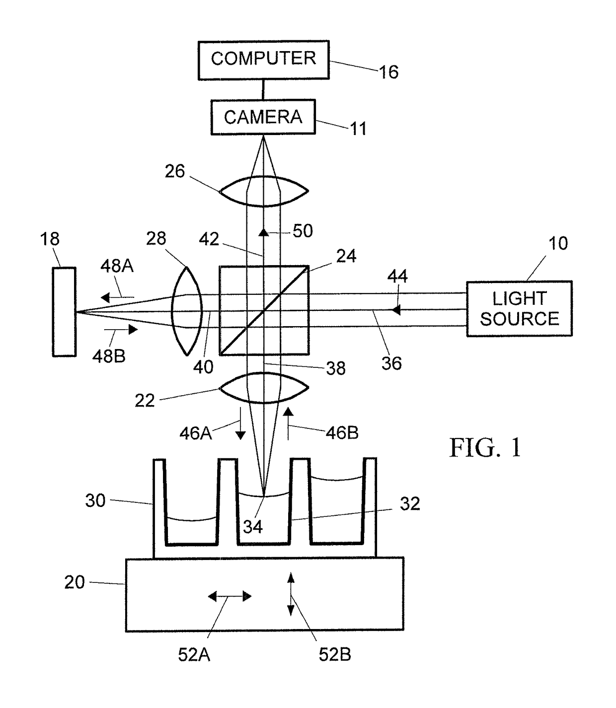
[0120]Camera 11 acquires a sequence of images. Between images, the optical path length difference between the sample and reference arms of the low-coherence optical interferometric ranging system is incremented. To that end, the difference between the optical path length of beam 40 and the optical path length of beam 38 is altered by vertically translating microplate 30 in the direction indicated by arrows 52B using translation stage 20. In an alternative embodiment, the reference mirror 18 could be translated relative to the beam splitter along the optical axis of beam 40 instead. If microplate 30 is translated relative to the detector, care is taken to ensure that the sample remains sufficiently in focus. For the short coherence lengths on the order of 10-20 μm of typical broadband light sources 10 suggested here, the maximum scan range that is needed to record an interferogram is much smaller than the working distance of the imaging lens (typically 25...

second embodiment

Operation Second Embodiment

Light Source and Optical Path Length Modulation

[0153]Light source 10 is operated in such a manner that it emits light of an intensity that remains substantially constant with time. A periodic electrical signal is applied to piezo-electric fiber stretcher 66, which causes it to periodically change the length of the optical path the light in the reference beam traverses. As an example, a triangular waveform may be applied. The frequency of the triangular waveform depends on the needs of the experiment and the characteristics of piezo-electric fiber stretcher 66. In particular, it determines an upper limit on how many elevation scans the instrument can perform in a given period of time. A frequency of between 200 and 2000 Hz is one suitable frequency range for the fiber stretchers used here. As an example, to measure the liquid fill height in a typical well 32 in a microplate 30, the following steps are taken. In order to measure the elevation of a point on t...


PUM


Abstract

An apparatus and method for the accurate and non-invasive measurement of the volume of liquid samples by optical interferometry. Small volumes of liquid samples are often contained in and partially fill the wells of a microplate. A low-coherence interferometric ranging system is used to determine the topography of the sample surface exposed by each well. The surface topography, together with the measured, or otherwise known, dimensions of the well, determine the volume of the liquid sample. Embodiment options include confining the optical beams of the interferometer to optical fiber and varying the optical-path length by piezo-electric stretching of a portion of the fiber. Other embodiment options include automation of data collection by stepping the microplate beneath the interferometer, pixelating the optical beam of the interferometer and scanning the microplate by scanning the sample beam of the interferometer with a mirror. Uniformity of the microplate wells is not required.

Description

CROSS REFERENCE TO RELATED APPLICATIONS[0001]This application is a continuation of application PCT / US2015 / 043,910, filed on Aug. 6, 2015, which claimed priority to U.S. Provisional patent application 62 / 036,142 filed on Aug. 12, 2014. The entire disclosures of both applications are incorporated herein by reference.BACKGROUND[0002]Field[0003]This invention relates in general to the measurement of liquid-sample volumes and, more specifically, to the use of low-coherence optical interferometry toward that end.[0004]Description of Related Art[0005]In a typical laboratory setting, several small reaction vessels are arranged in a rectangular microplate. These microplates have standardized, common outer dimensions and contain a varying number of vessels, which are referred to as wells. The most common cases are 96, 384, and 1536 wells. The volume of the individual well decreases as the well density of the plate increases. Standardized microplates allow for the use of automated liquid deliv...

Claims


Application Information

Patent Timeline
IPC IPC(8): G01F23/292G01B9/02
CPCG01B9/0209G01F23/292G01B11/00G01F23/2928
Inventor LUEDEMANN, HANS-CHRISTIAN
Owner LUEDEMANN HANS CHRISTIAN
Why Eureka
Try Eureka