
Permanent magnet generator case vent valve

Active Publication Date: 2019-01-17
HAMILTON SUNDSTRAND CORP
View PDF4 Cites 0 Cited by
  • Summary
  • Abstract
  • Description
  • Claims
  • Application Information

AI Technical Summary

Benefits of technology

The patent describes an electric generator that has a rotor and stator inside a housing. A seal prevents lubricant from leaking out of the housing. A vent valve helps to vent the interior of the housing when the rotor shaft is not rotating. The technical effect of this design is to improve the efficiency and reliability of the electric generator.

Problems solved by technology

However, in the past, the relief valves have opened an undesirably high number of times under some applications due to the pressure build up from the lift off seal.
This is, of course, undesirable because with several cycles, eventually the generator could become low in oil before the normal service interval.

Method used


Image

  • Permanent magnet generator case vent valve
  • Permanent magnet generator case vent valve

Examples


Embodiment Construction

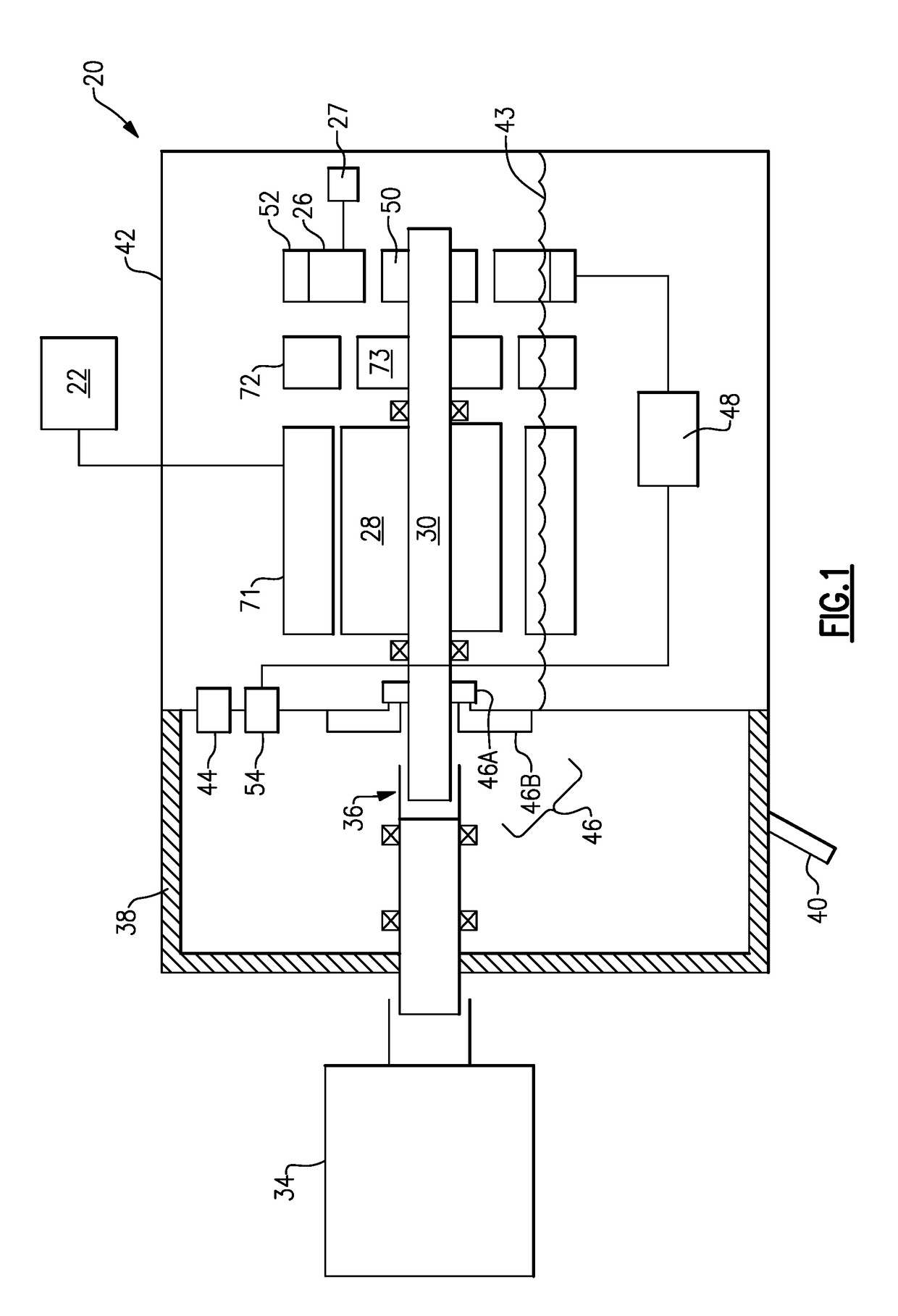
[0013]FIG. 1 shows an electric generator assembly 20. As known, the generator generates electricity for a use 22, shown schematically. In one application, this generator is a permanent magnet generator and the use 22 may be for various uses of electricity on an aircraft.

[0014]However, it should be understood that other types of generators besides permanent magnet generators and other uses besides aircraft applications may benefit from the teachings of this disclosure.

[0015]Generator stator coils 71 are positioned outwardly of a permanent magnet rotor 28. The stator 71 and rotor 28 are in operable communication to generate electricity. The permanent magnet rotor 28 rotates with a generator shaft 30. A shaft 32 extends outwardly of a housing 38 and to a source of rotation 34. In one application, the source of rotation 34 may be a gas turbine engine, such as found on aircraft engines. Again, other sources of rotation may be utilized.

[0016]A gear connection 36 is shown schematically. As...


PUM


Abstract

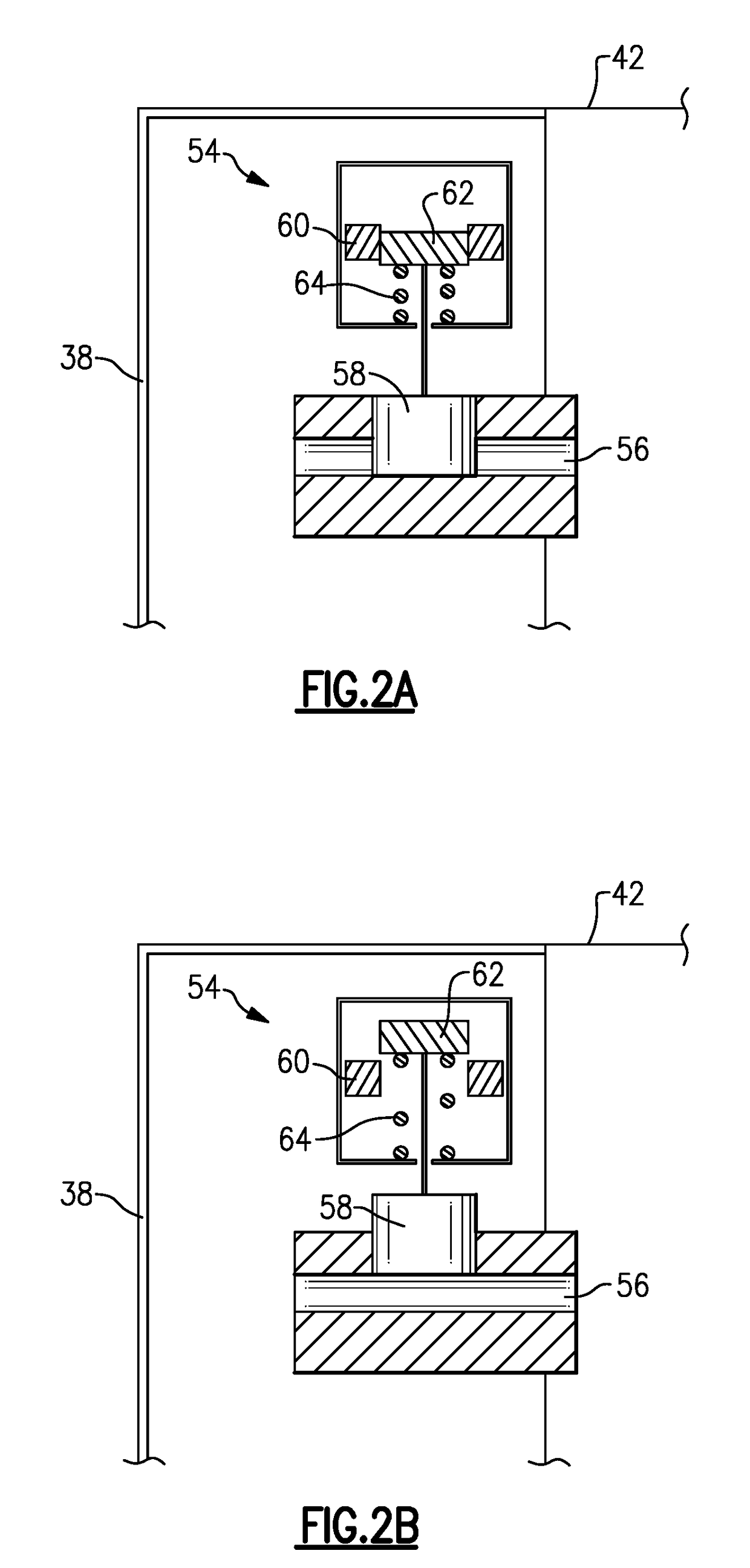
An electric generator has a rotor shaft to be driven to rotate with a generator rotor. A generator stator is positioned adjacent the generator rotor. A housing surrounds the generator rotor and the generator stator. The generator rotor shaft extends outwardly of the housing. A seal seals a location where the rotor shaft extends outwardly of the housing. A vent valve is configured to vent of the interior of the housing when the rotor shaft is not rotating. An electrical assembly is also disclosed. An electrical assembly is also disclosed.

Description

BACKGROUND OF THE INVENTION[0001]This application relates to an electrical generator wherein a vent valve is provided to vent the interior of a housing case at shutdown.[0002]Electric generators are known and typically include a shaft driven by a source of rotation to rotate a generator rotor adjacent to a generator stator. With this rotation, electricity is generated and used for any number of uses.[0003]One known electric generator is housed in a housing and a generator rotor shaft extends outwardly of the housing. A liftoff seal is provided to seal the location where the shaft leaves the housing. As known, liftoff seals can gradually build up internal case pressure of the generator on subsequent start-stop cycles.[0004]It is also known to provide a pressure relief valve on the housing case to allow venting of the interior of the housing case should a pressure become undesirably high. However, in the past, the relief valves have opened an undesirably high number of times under som...

Claims


Application Information

Patent Timeline
IPC IPC(8): F16K31/06F16K31/04F16K31/10H01F7/02H02K35/02
CPCF16K31/0627F16K31/046F16K31/0606F16K31/10H01F7/0273H02K35/02F16K24/04H02K5/10H02K5/124H02K7/116H02K2205/09H02K2213/09H02K9/193
Inventor GROSSKOPF, ANDREW P.
Owner HAMILTON SUNDSTRAND CORP
Learn More