Chassis for a Rail Vehicle

a rail vehicle and chassis technology, applied in the direction of railway components, electric motor propulsion transmissions, chassis frames, etc., can solve the problems of reducing the proportion of the chassis frame itself smoothing out track twists, affecting the maintenance effect, and reducing the torsional load. , to achieve the effect of simple and low-cost interfaces

Active Publication Date: 2019-01-31
SIEMENS MOBILITY AUSTRIA GMBH
View PDF0 Cites 0 Cited by
  • Summary
  • Abstract
  • Description
  • Claims
  • Application Information

AI Technical Summary

Benefits of technology

[0028]This measure brings about simple and low-cost interfaces for the arrangement of the drive motor on the chassis frame. A reduction in the torsional loads on the open profiles is further achieved via this measure.
[0029]An advantageous embodiment is obtained if at each end of the first longitudinal carrier a first primary spring cup and a second primary spring cup are provided, and the third elastic bearing is arranged between the first primary spring cup and the second primary spring cup. This measure creates a concentration of the application of force on the first longitudinal carrier and on the second longitudinal carrier in the area of the first primary spring cup and of the second primary spring cup, and thus a reduction in the load on the first longitudinal carrier and on the second longitudinal carrier from torques.
[0030]It is favorable if the first elastic bearing, the second elastic bearing and the third elastic bearing are arranged such that they form the corner points of a triangle in a horizontal plane, and if the drive motor is arranged such that the horizontal center of gravity of the drive motor is located within the triangle. This measure leads to a homogenization of the load on the first elastic bearing, the second elastic bearing and the third elastic bearing.

Problems solved by technology

Derailment safety, on the one hand, and requirements stemming from the calculation of vehicle construction gauges, for example in accordance with Leaflet 505-1 of the Union internationale des chemins de fer (UIC) or the European Standard (EN) 15273, on the other, frequently lead to design conflicts, which will leave a greater proportion of the chassis frame itself smoothing out track twists than is desirable.
The above-cited conventional approaches each have the disadvantage of a joint suspension of a drive motor and a transmission on a chassis frame of a chassis.
In addition, because of a swash plate arranged between the drive motor and the transmission, separate demountability of the drive motor and of the transmission for maintenance purposes is not provided for the described conventional approaches.

Method used


Image

  • Chassis for a Rail Vehicle
  • Chassis for a Rail Vehicle
  • Chassis for a Rail Vehicle

Examples


Embodiment Construction

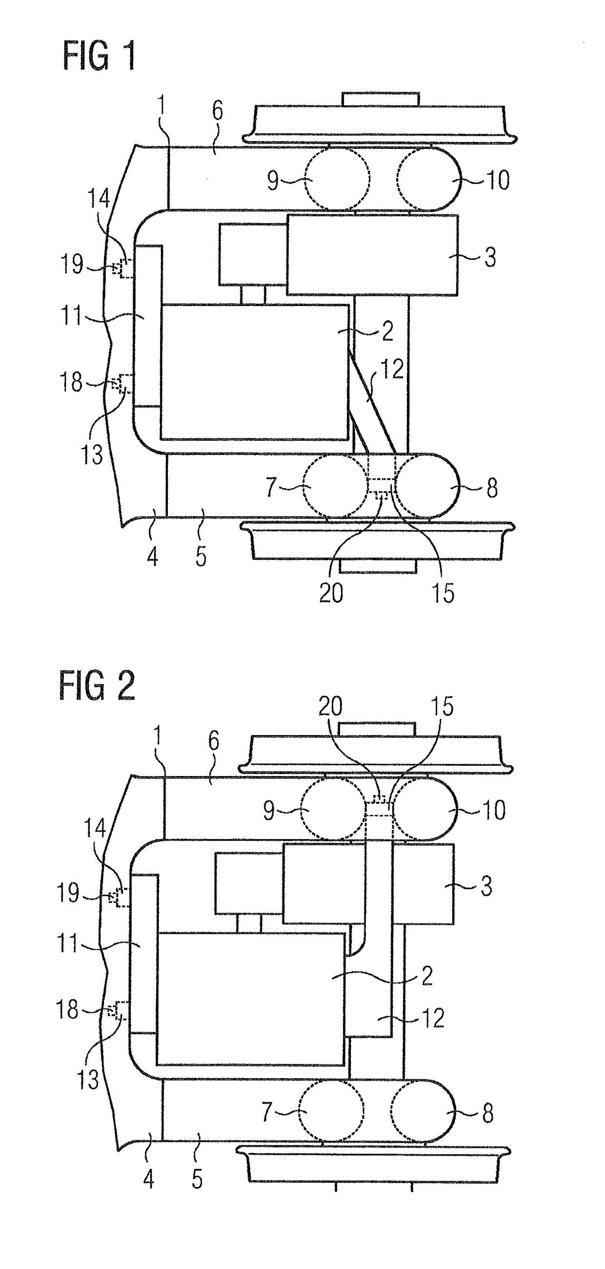
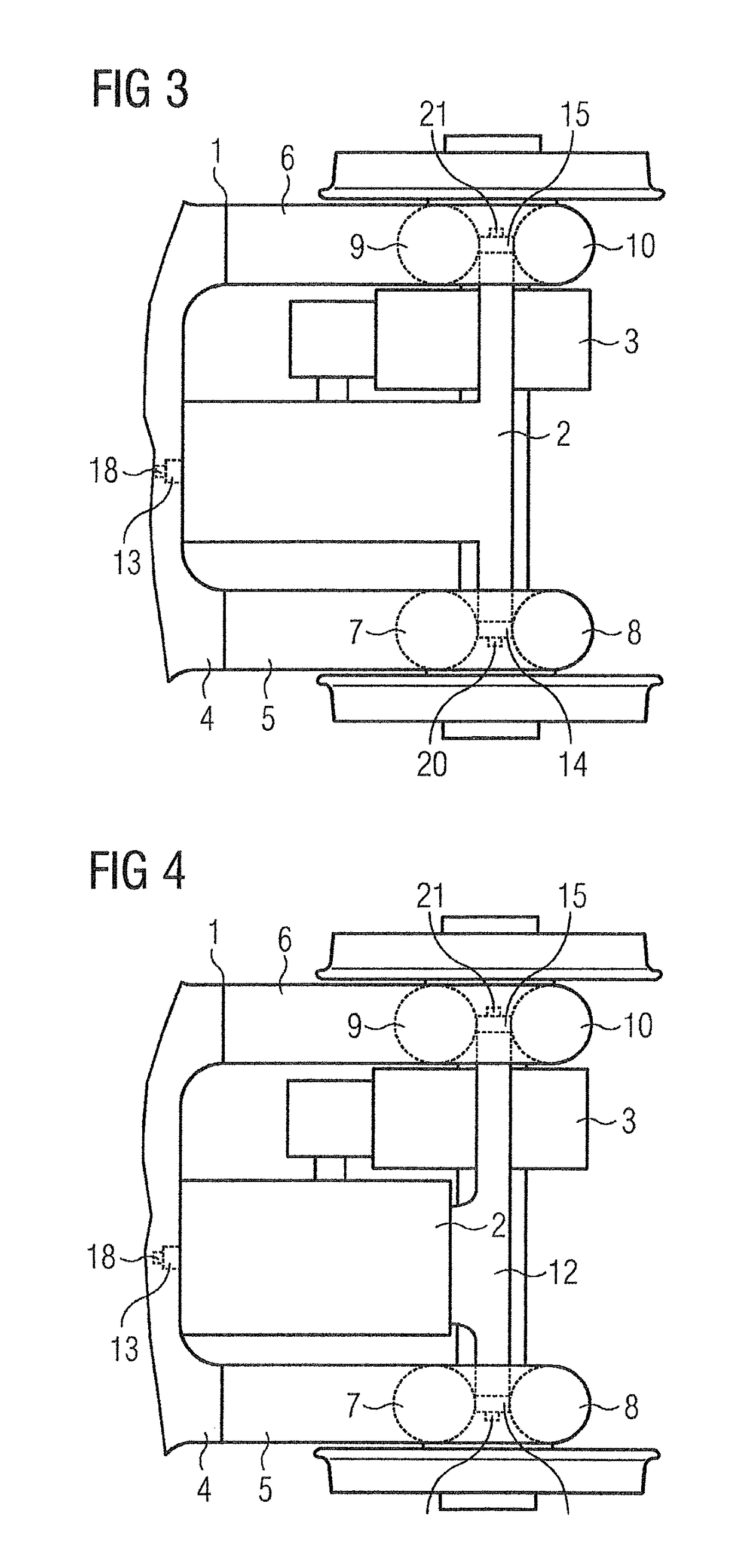
[0041]An extract from a first, exemplary embodiment of an inventive chassis shown in top view in FIG. 1, comprises a chassis frame 1, a transversely mounted drive motor 2, a transmission 3, a crossmember 4, a first longitudinal carrier 5, a second longitudinal carrier 6, and a first primary spring cup 7, a second primary spring cup 8, a third primary spring cup 9 and a fourth primary spring cup 10. In an advantageous embodiment, the crossmember 4 is manufactured from open profiles. The first longitudinal carrier 5 and the second longitudinal carrier 6 are, for example, welded to the crossmember 4.

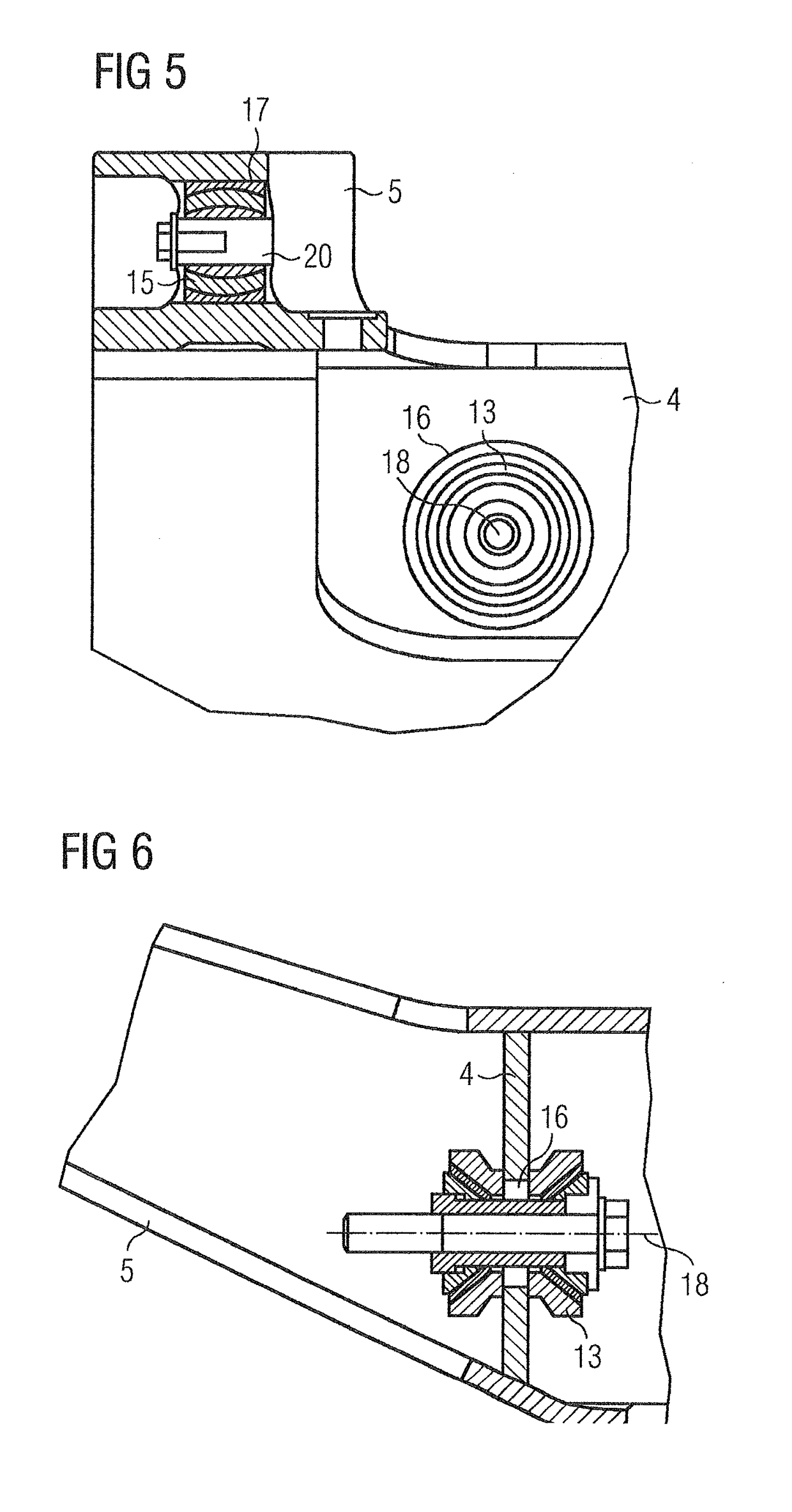
[0042]The drive motor 2 is connected to the crossmember 4 via a first attachment module 11, upon which are arranged a first elastic bearing 13 and a second elastic bearing 14.

[0043]The drive motor 2 is connected to the first longitudinal carrier 5 via a second attachment module 12 and third elastic bearing 15 arranged thereon. A particularly advantageous three-point suspension thereby resul...


PUM


Abstract

A chassis for a rail vehicle, in particular with inboard wheel sets, with at least one transmission, at least one transversely mounted drive motor and at least one chassis frame, wherein the chassis frame includes at least one crossmember and at least a first longitudinal carrier and a second longitudinal carrier, where at least a first elastic bearing, a second elastic bearing and a third elastic bearing are arranged between the drive motor and the chassis frame, and where in each case one of the elastic bearings is arranged on at least one of the longitudinal carriers in order to provide advantageous construction conditions.

Description

CROSS-REFERENCE TO RELATED APPLICATIONS[0001]This is a U.S. national stage of application No. PCT / EP2017 / 051591 filed Jan. 26, 2017. Priority is claimed on Austrian Application No. A50054 / 2016 filed Feb. 1, 2016, the content of which is incorporated herein by reference in its entirety.BACKGROUND OF THE INVENTION1. Field of the Invention[0002]The invention relates to a chassis for a rail vehicle, in particular with inboard wheel sets, with at least one transmission, at least one transversely mounted drive motor, and with at least one chassis frame, which comprises at least one crossmember, at least one first longitudinal carrier and one second longitudinal carrier.2. Description of the Related Art[0003]Chassis for rail vehicles must be safe against derailment. Derailment safety can be achieved via the chassis reacting in a flexible manner to track twists. Flexibility in relation to track twists is customarily realized in the first instance via a corresponding embodiment of a primary ...

Claims


Application Information

Patent Timeline
Patent Type & Authority Applications(United States)
IPC IPC(8): B61C9/48B61F3/04B61F13/00B61F1/06
CPCB61C9/48B61F3/04B61F13/00B61F1/06B61C9/50B61F3/06B61F5/50
Inventor FALKENSTEIN, MARKOKUETER, CHRISTIANMONTESI-HEIMERL, KLAUSTEICHMANN, MARTINWEILGUNI, GERHARDZIERLER, STEFANGONZALEZ LARRACHE, XABIERSEIFRIED, RADOVAN
Owner SIEMENS MOBILITY AUSTRIA GMBH
Why Eureka
Try Eureka