
Locking in-place small form factor pluggable transceiver module

a technology of plug-in transceivers and transceivers, applied in electromagnetic transceivers, multi-mode transmission, instruments, etc., can solve the problems of limiting the use of sfp optical transceivers in such environments, the prong retaining mechanism is not durable enough to stand, and the current solution for fixing sfp optical transceivers in place is limited

Active Publication Date: 2019-01-31
SIEMENS CANADA LTD
View PDF13 Cites 3 Cited by
  • Summary
  • Abstract
  • Description
  • Claims
  • Application Information

AI Technical Summary

Benefits of technology

The present invention provides a locking plug mechanism for SFP optical transceivers that allows them to be easily fixed in place when connected to a network device. This mechanism offers flexibility for easy swapping and reconfiguration of switch / router platforms. The SFP optical transceivers can be installed in different environments where reconfiguration is needed, for example, in networking applications. The technical effects of the invention include improved fixedness and accessibility of SFP optical transceivers for network devices.

Problems solved by technology

This single prong retaining mechanism is not durable enough to stand up to heavy shock and vibration environments, greatly limiting the use of SFP optical transceivers in such environments.
Current solutions for fixing SFP optical transceivers in place have been limited to use of glue to permanently fix the SFP optical transceiver in place.
However, this approach greatly limits the flexibility offered by SFP optical transceivers because it eliminates the easy swapping and reconfigurability of switch / router platforms.
In addition, it forces an entire module to be removed should a single SFP optical transceiver fail.

Method used


Image

  • Locking in-place small form factor pluggable transceiver module
  • Locking in-place small form factor pluggable transceiver module
  • Locking in-place small form factor pluggable transceiver module

Examples


Embodiment Construction

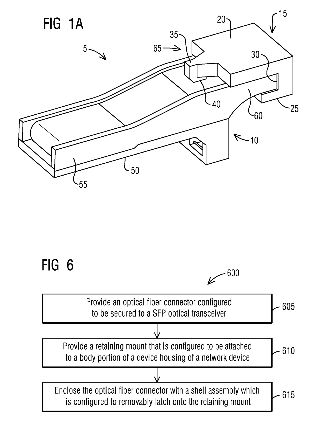
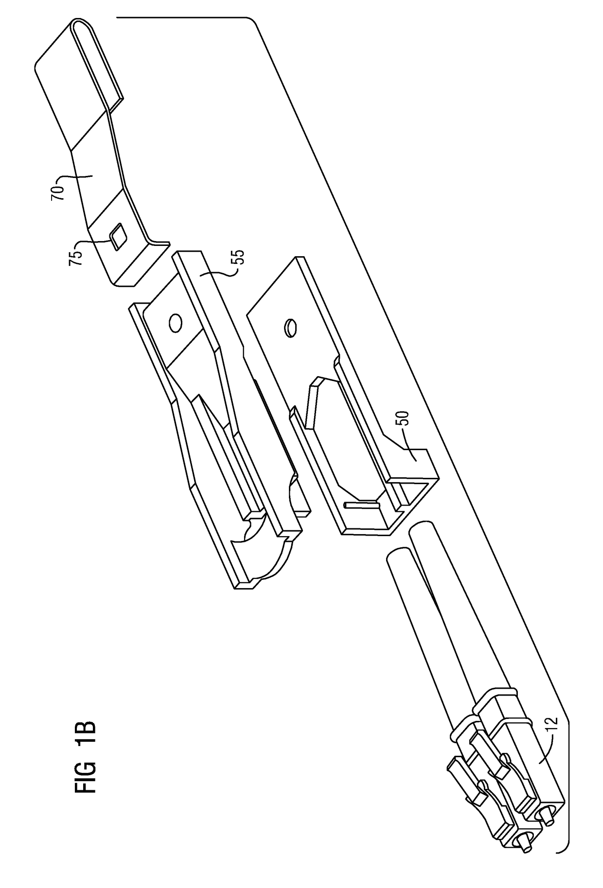
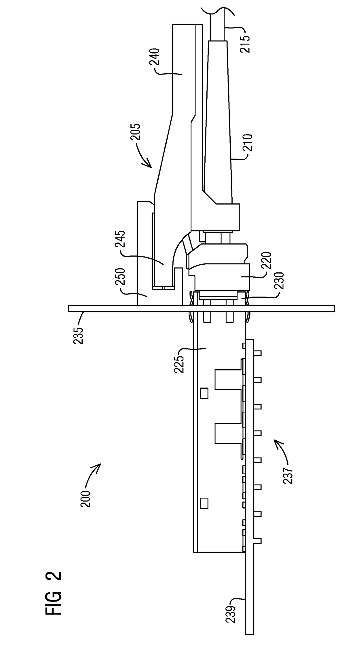
[0018]To facilitate an understanding of embodiments, principles, and features of the present invention, they are explained hereinafter with reference to implementation in illustrative embodiments. In particular, they are described in the context of securely attaching an optical fiber connector and a SFP optical transceiver to a retaining mount attached to a body portion of a device housing of a network device by inserting a portion of a body of a shell assembly enclosing the optical fiber connector into the retaining mount. Embodiments of the present invention, however, are not limited to use in the described devices or methods.

[0019]The components and materials described hereinafter as making up the various embodiments are intended to be illustrative and not restrictive. Many suitable components and materials that would perform the same or a similar function as the materials described herein are intended to be embraced within the scope of embodiments of the present invention.

[0020]...


PUM


Abstract

A small form factor pluggable (SFP) optical transceiver module is provided. It includes a shell assembly that encloses an optical fiber connector configured to connect to a SFP optical transceiver and a retaining mount that is configured to be attached to a body portion of a device housing of a network device. The SFP optical transceiver is configured to interface a network device motherboard to a fiber optic at a given port of the network device. The shell assembly is configured to removably latch onto the retaining mount. The shell assembly includes a base and a body coupled to each other. The body has a latch to securely attach the optical fiber connector and the SFP optical transceiver to the retaining mount while allowing the SFP optical transceiver to be swapped as needed to reconfigure the given port of the network device.

Description

BACKGROUND1. Field[0001]Aspects of the present invention generally relate to providing communications such as via a small form factor pluggable (SFP) transceiver and more specifically relates to retaining SFP transceivers in place when they are mounted onto a network device.2. Description of the Related Art[0002]An optical transmitter and / or receiver such as a small form factor pluggable (SFP) optical transceiver includes a housing with appropriate electrical circuitry that interfaces with other optical communications equipment. The front face of the housing includes a receptacle for receiving a fiber optic connector to which an optical fiber cable is terminated. The optical transmitter and receiver are interconnected by the optical fiber cable.[0003]SFP optical transceivers are useful in improving the configurability of products by allowing transceivers to be swapped as needed to reconfigure the given ports for the needed link range and media type. The SFP standard prescribes a sin...

Claims


Application Information

Patent Timeline
IPC IPC(8): G02B6/38G02B6/42H04B10/40H04B10/2581
CPCG02B6/3897G02B6/3879G02B6/4292G02B6/4246H04B10/40H04B10/2581G02B6/3893G02B6/38G02B6/42
Inventor APRO, ATTILA
Owner SIEMENS CANADA LTD
Learn More