
Telepresence robot

a technology of telepresence robots and robots, applied in the field of personal robots, can solve the problems of many limitations of a typical video conference set up, many limitations that limit their functionality, and many do not have the ability to rotate or tilt their head

Inactive Publication Date: 2019-01-31
ENG SERVICES INC
View PDF1 Cites 5 Cited by
  • Summary
  • Abstract
  • Description
  • Claims
  • Application Information

AI Technical Summary

Benefits of technology

This patent describes a telepresence robot that can be controlled by a remote computing device. The robot has a base, body, neck, head, and tilt mechanism. The tilt mechanism can tilts the head forward and backward by at least 10 degrees. The head can also rotate from a neutral position. The robot has cameras for both front and rear views, and a navigation camera for pointing forward. The remote computing device can display the images from the cameras and has a user interface for controlling the robot's movement. The robot can be connected to a docking station for recharging. The technical effect of this patent is that it allows for easy control and adjustment of a telepresence robot through a remote computing device.

Problems solved by technology

However, there are many limitations to a typical video conference set up.
There are some telepresence robots available however they have several limitations that limit their functionality.
Of those telepresence robots currently on the market, many do not have the ability to rotate or tilt their head (pan / tilt).
This is a severe design limitation as the ability to look around is an important feature for the user to fully participate in the meeting.
Furthermore, of those designs which do incorporate the flexibility of pan / tilt, none meet some specific requirements that would allow for full participation of the user during the video teleconferencing operation.
However, there are some limitations.
Even though RP-Vita uses a coreless motor which is self-supporting and has high power-to-volume characteristics, the single direct connection between display and motor are too weak to hold the display stably in the tilt direction.
Therefore, the inherent limitation in the use of such pan-tilt motion is that the tilt direction mechanical structure is too weak to hold the display of the robot in limited positions.
Because the range of motion of the RP-Vita head is limited, it can only be used in specific situations.

Method used


Image

  • Telepresence robot
  • Telepresence robot
  • Telepresence robot

Examples


Embodiment Construction

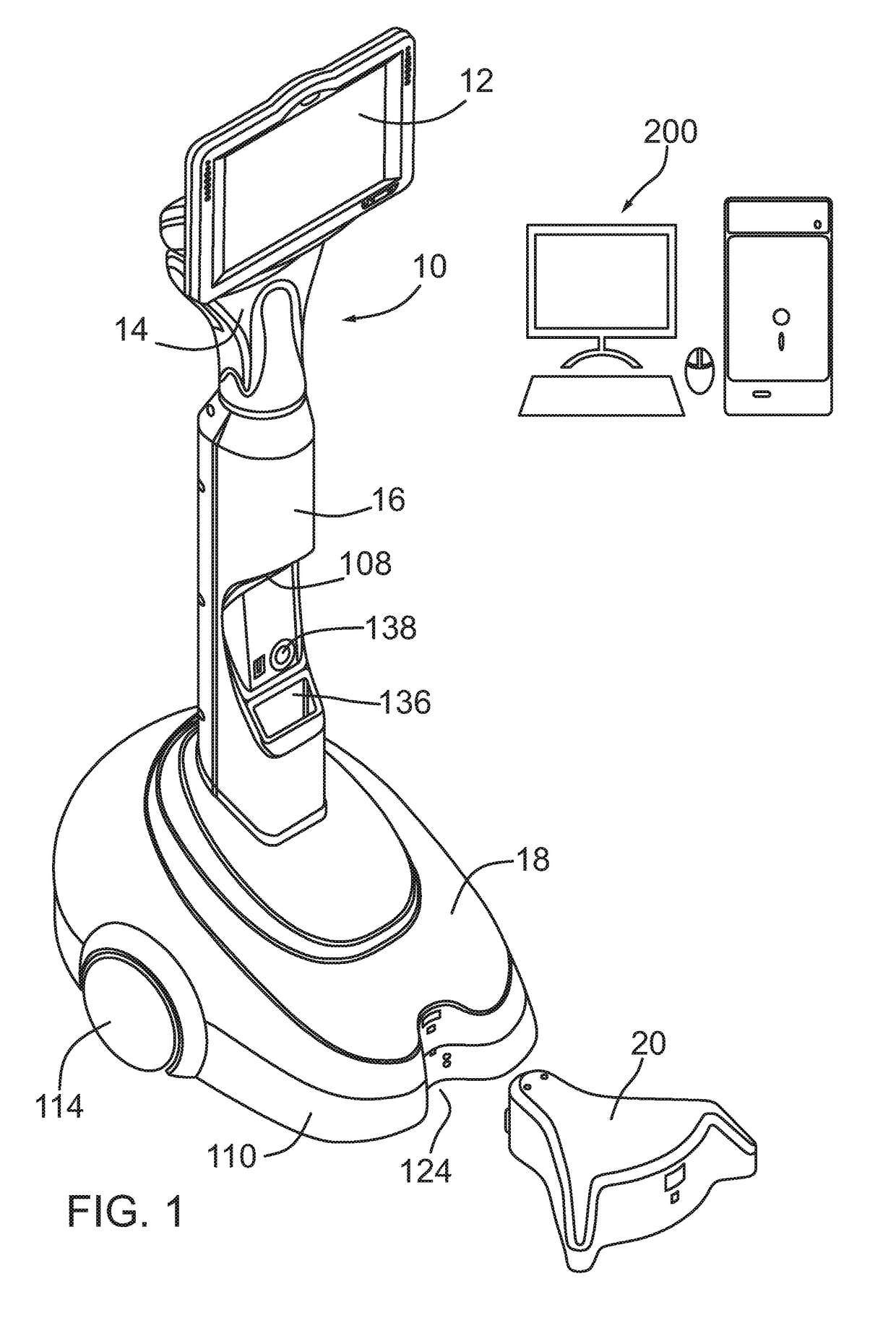
[0051]Referring to FIG. 1 the telepresence robot is shown generally at 10. The telepresence robot 10 includes a head 12, a neck 14, a body 16 and a base or platform 18. The telepresence robot 10 may be charged with a docking station 20.

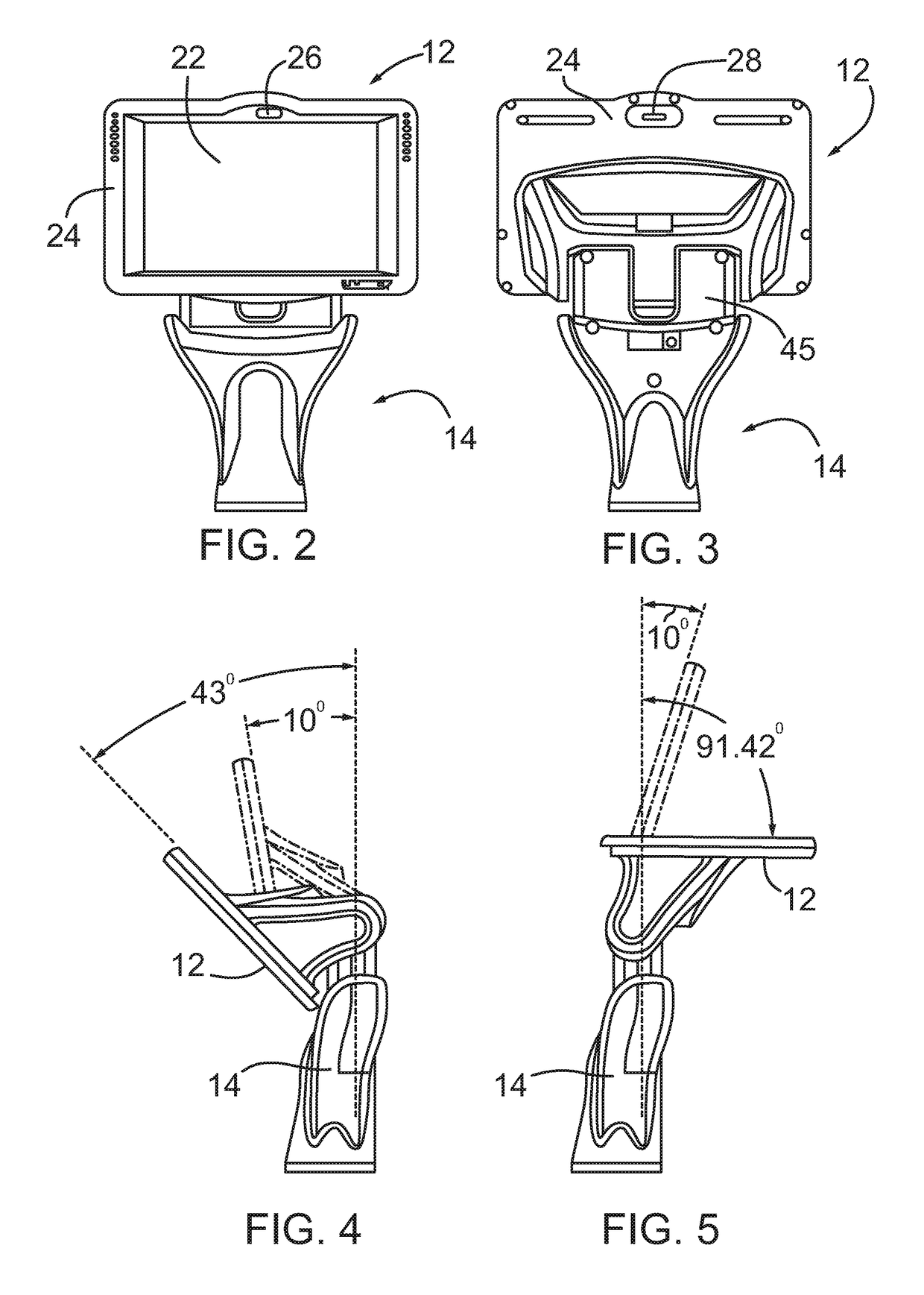
[0052]Referring to FIGS. 2 to 5, the head 12 includes a screen or display 22 and a screen housing 24. The screen 22 may be a touch screen and may be an off the shelf tablet or a purpose-built screen. The screen 22 includes a front head camera 26 and a back-head camera 28. In an embodiment, the screen is a 12-inch screen which uses Windows™ 10. However, this may vary based on the needs of the user. The head 12 can tilt to from at least 10 degrees forwardly and preferably to over 40 degrees forwardly from a generally upright position as shown in FIG. 4. As well the head can tilt to from at least 10 degrees backwardly and preferably to over 90 degrees backwardly from a generally upright position as shown in FIG. 5. This tilting feature provides the telep...


PUM


Abstract

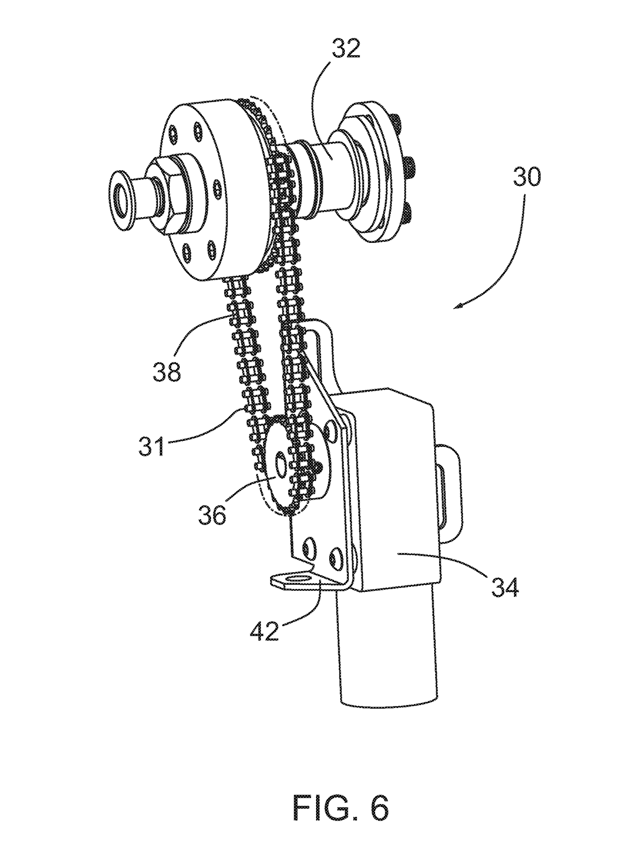
A telepresence robot for use in association with a remote computing device includes a base, a body, a neck, a head and a tilt mechanism. The base has a drive system in communication with the remote computing device. The body is operably attached to the base. The neck is operably attached to the body. The head is operably attached to the neck. The head has a screen and the screen is in communication with the remote computing device. The tilt mechanism connects the head to the neck. The tilt mechanism includes a chain and sprocket assembly whereby the head tilts at least 10 degrees forwardly from a generally upright position and at least 10 degrees backwardly form the generally upright position.

Description

FIELD OF THE DISCLOSURE[0001]This disclosure relates to personal robots and in particular telepresence robots that are able to provide human to human video and audio conferencing otherwise known as telepresence.BACKGROUND[0002]The use of video conferencing has in recent years become an important tool for many businesses. However, there are many limitations to a typical video conference set up. Specifically, the person joining the conference by way of video conference typically has little or no control over who they are looking at. The limitations of video conferencing and other issues related to working with a team from a remote location have generated a new type of robot often referred to as a telepresence personal robot. A telepresence robot typically combines the freedom of mobility with video conferencing. This combination provides an improved experience over video conferencing and that improves people's connection with clients, employees and teammates.[0003]There are some telep...

Claims


Application Information

Patent Timeline
Patent Type & Authority Applications(United States)
IPC IPC(8): G05D1/00G05D1/02G06F3/0484B25J9/16H04N7/14
CPCG05D1/0038G05D1/0231G06F3/0484B25J9/1689H04N7/148B25J11/00B25J19/023H04N7/142H04N7/15B25J9/0009B25J9/1005B25J19/005B25J19/02
Inventor WANG, CHINJOHNHUANG, QING
Owner ENG SERVICES INC
Learn More