X-ray radiographic apparatus, method of measuring head tilt in taking radiograph, stand for x-ray radiographic apparatus, chair for x-ray radiographic apparatus, and head tilt setting device

a radiographic and x-ray technology, applied in the field of x-ray radiographic apparatus, can solve the problems of varying head tilt, face, etc. of patients, and it is absolutely difficult that posteroanterior cephalometric radiograph and lateral cephalometric radiograph are taken under the same head tilt of a patient, and achieve the effect of high reproducibility

Active Publication Date: 2015-06-18
CEPHMEDICAL
View PDF1 Cites 4 Cited by
  • Summary
  • Abstract
  • Description
  • Claims
  • Application Information

AI Technical Summary

Benefits of technology

[0040]According to the present invention, a lateral cephalometric radiograph, a posteroanterior cephalometric radiograph, an anteroposterior cephalometric radiograph, and a cephalometric radiograph in any direction between the posteroanterior direction and the anteroposterior direction, etc. can be taken under the same tilt in the front-rear direction of the head of a subject easily and with high reproducibility, moreover there is no risk associated with the use of an infraorbital point pointing bar.

Problems solved by technology

For this, it is considered to be absolutely difficult that a posteroanterior cephalometric radiograph and a lateral cephalometric radiograph are taken under the same head tilt of a patient.
Also, the method has a risk which the face, etc. of a patient would contact with the infraorbital point pointing bar.
Also, according to the method of the Non-Patent Literature 3, when taking a lateral cephalometric radiograph, not to mention a posteroanterior cephalometric radiograph, it is inevitable that the head tilt varies every time taking a cephalometric radiograph, and it is considered that taking a posteroanterior cephalometric radiograph and a lateral cephalometric radiograph under the same head tilt of a patient is very difficult.

Method used


Image

  • X-ray radiographic apparatus, method of measuring head tilt in taking radiograph, stand for x-ray radiographic apparatus, chair for x-ray radiographic apparatus, and head tilt setting device
  • X-ray radiographic apparatus, method of measuring head tilt in taking radiograph, stand for x-ray radiographic apparatus, chair for x-ray radiographic apparatus, and head tilt setting device
  • X-ray radiographic apparatus, method of measuring head tilt in taking radiograph, stand for x-ray radiographic apparatus, chair for x-ray radiographic apparatus, and head tilt setting device

Examples


first embodiment

1. The First Embodiment

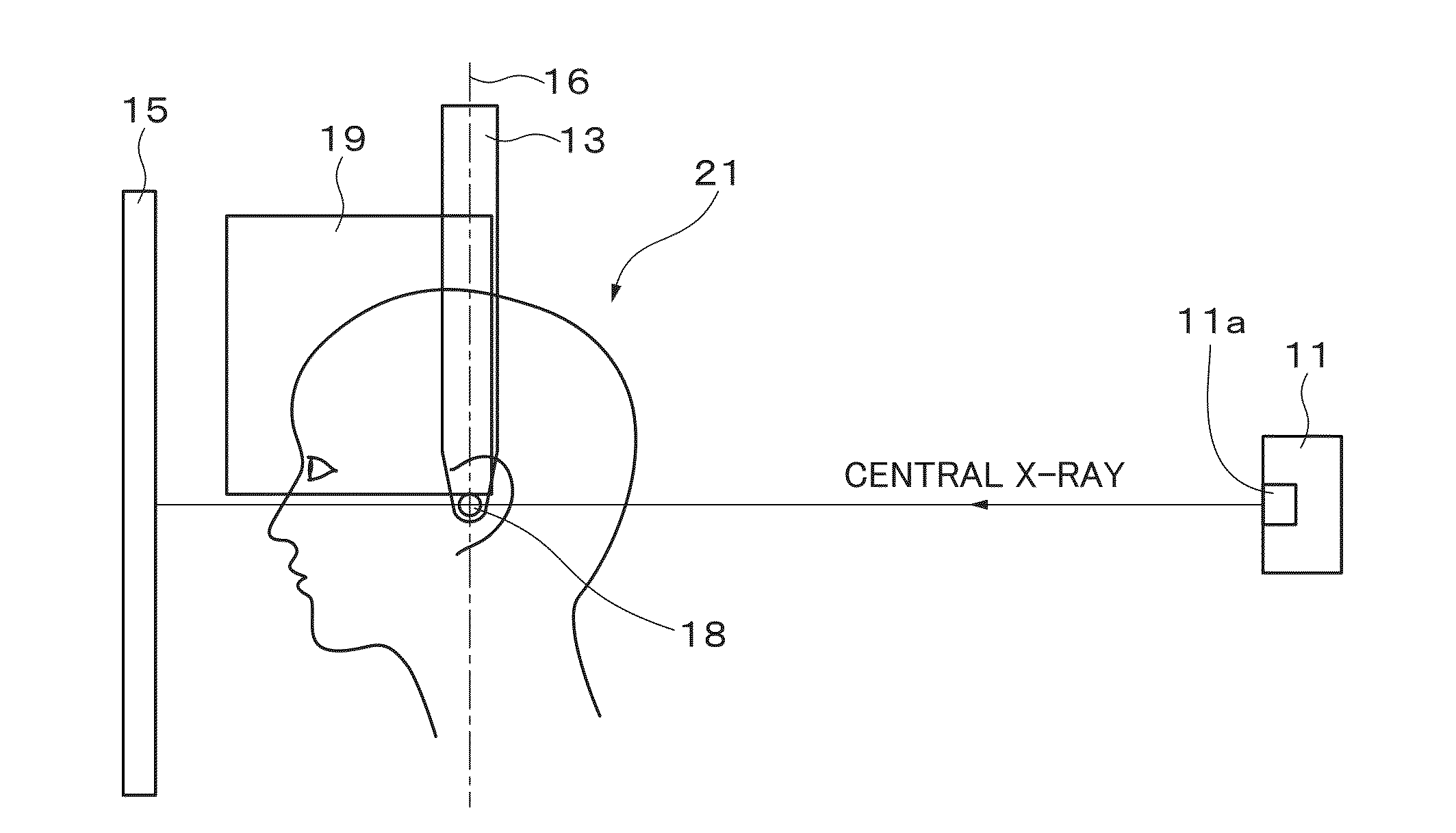
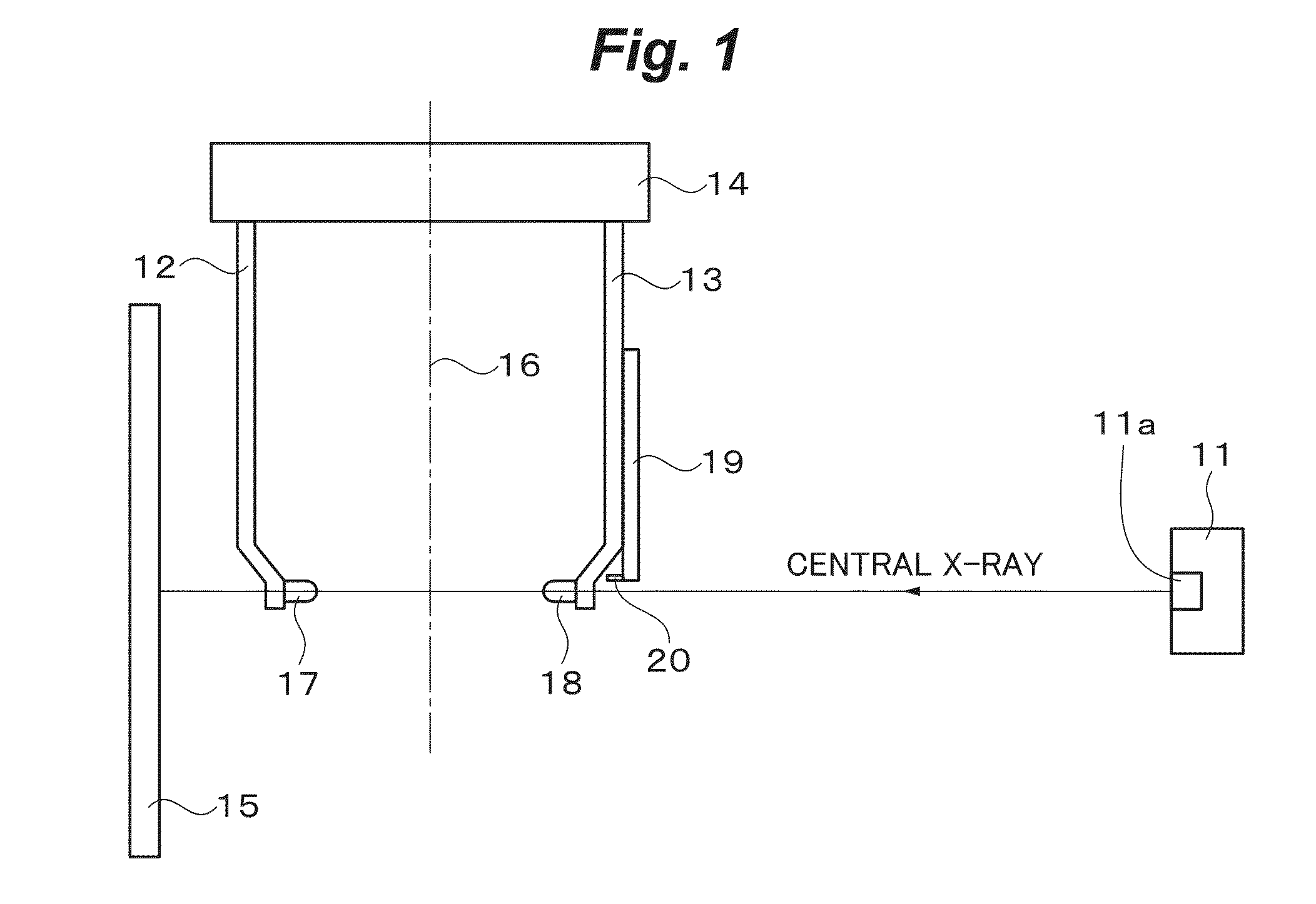
[0120]FIG. 1 shows the cephalometric X-ray radiographic apparatus according to the first embodiment. As shown in FIG. 1, the cephalometric X-ray radiographic apparatus has an X-ray generator 11, arms 12 and 13, an arm control device 14, and an X-ray detector 15. The X-ray generator 11 has an X-ray tube 11a, and from the X-ray tube 11a, the X-ray is generated. The arm control device 14 is supported for the floor surface by a support part of which drawing is omitted.

[0121]The X-ray generated from the X-ray tube 11a is irradiated to the head of a subject, the X-ray transmitted through the head enters into the X-ray detector 15, and the transmission X-ray image is obtained. The X-ray detector 15 is not specifically limited, but, for example, an X-ray film, an imaging plate, a semiconductor detector, etc. are used. The transmission X-ray image is, as necessary, converted to a digital image signal, for example.

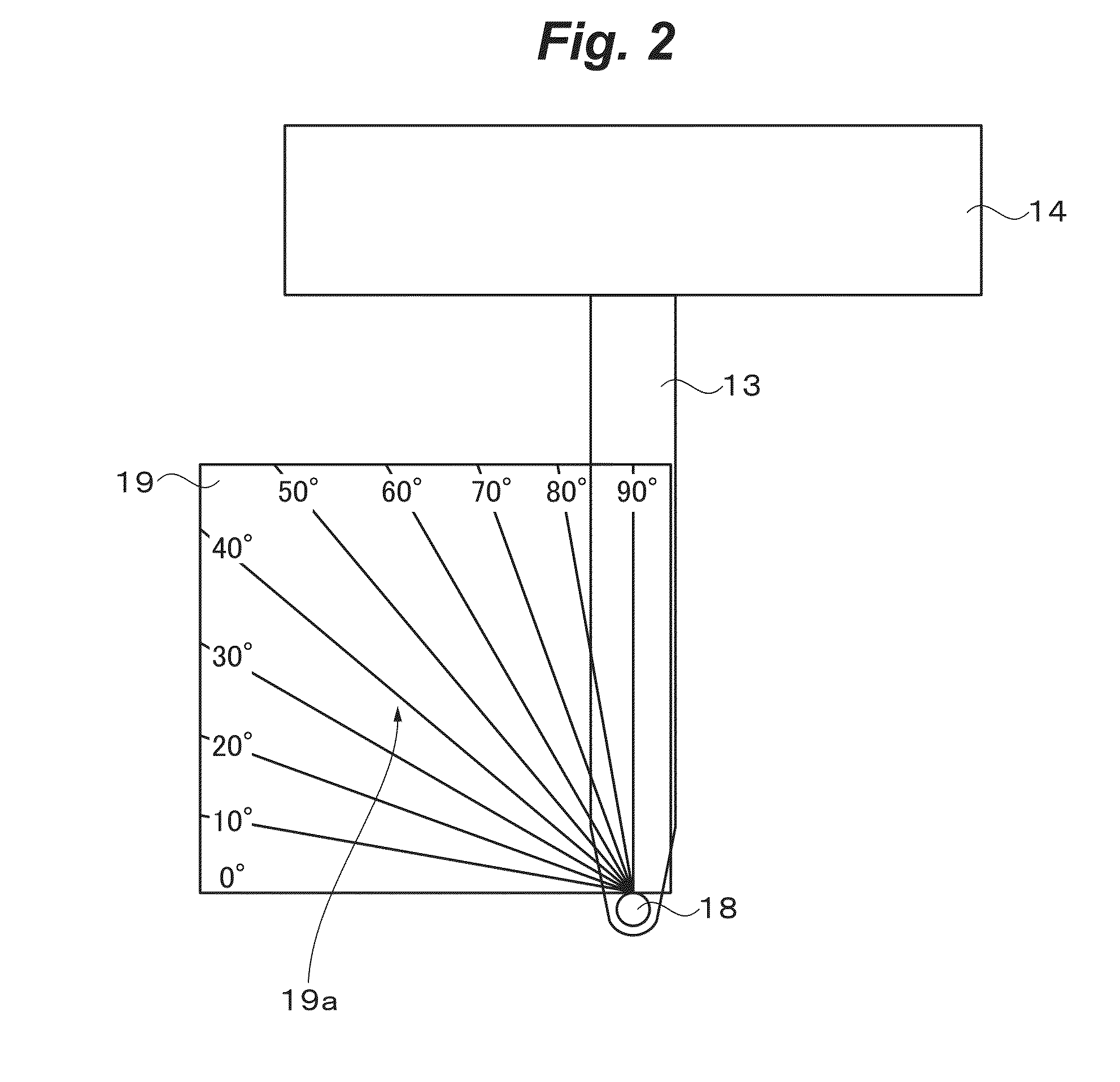
[0122]The arms 12 and 13 are provided facing each other ...

second embodiment

2. The Second Embodiment

[0133]In the cephalometric X-ray radiographic apparatus according to the second embodiment, unlike the cephalometric X-ray radiographic apparatus according to the first embodiment, the head tilt setting device 19 is not provided to the arm 13, but the head tilt setting device 19 is provided to a stand for X-ray radiographic apparatus attached to the cephalometric X-ray radiographic apparatus.

[0134]FIG. 11 shows the stand for X-ray radiographic apparatus. As shown in FIG. 11, the stand for X-ray radiographic apparatus has a support platform 51 to be placed on the floor surface, a support bar 52 being stood vertically to the support platform 51, and the head tilt setting device 19 fixed to the upper edge of the support bar 52. The support bar 52 is constituted telescopically, and its length can be adjusted within a predetermined range. For this, by adjusting the length of the support bar 52, the height of the head tilt setting device 19 can be adjusted, and by ...

third embodiment

3. The Third Embodiment

[0141]In the cephalometric X-ray radiographic apparatus according to the third embodiment, unlike the cephalometric X-ray radiographic apparatus according to the first embodiment, the head tilt setting device 19 is not provided to the arm 13, but the head tilt setting device 19 is provided to a chair for X-ray radiographic apparatus attached to the cephalometric X-ray radiographic apparatus.

[0142]FIG. 12 shows the chair for X-ray radiographic apparatus. As shown in FIG. 12, the chair for X-ray radiographic apparatus has a support platform 61 to be placed on the floor surface, a support bar 62 being stood vertically to the support platform 61, a main part 63 provided to the upper edge of the support bar 62, a support member 64 provided to the main part 63, and the head tilt setting device 19 provided to the upper edge of the support member 64. The main part 63 is comprised of a seating face 63a and a backrest 63b. The support bar 62 is constituted telescopicall...


PUM


Abstract

Provided is an X-ray radiographic apparatus that can take a lateral cephalometric radiograph, a posteroanterior cephalometric radiograph, etc. under the same state of the tilt in the front-rear direction of the head of a subject easily and with high reproducibility, and is free of risks associated with the use of an infraorbital point pointing bar.The X-ray radiographic apparatus comprises: a pair of arms provided facing each other with a reference line therebetween; ear rods provided to mutually facing inside surfaces of the pair of arms; a head tilt setting device for setting the tilt in the front-rear direction of the head of the subject provided on one arm, and a horizontal plane verification mechanism provided on the head tilt setting device or outside of the head tilt setting device.

Description

TECHNICAL FIELD[0001]The present invention relates to an X-ray radiographic apparatus, a method of measuring head tilt in taking a radiograph, a stand for X-ray radiographic apparatus, a chair for X-ray radiographic apparatus and a head tilt setting device which are suitable, for example, for applying in taking a cephalometric radiograph by a cephalometric X-ray radiographic apparatus.BACKGROUND ART[0002]In an orthodontic treatment, etc., when deciding a treatment plan, generally, taking a cephalometric radiograph (cephalogram) of a patient, and based on the cephalometric radiograph, the cephalometric analysis is performed (for example, see Non-Patent Literatures 1 and 2). Conventionally, as a cephalometric radiograph, a lateral (side surface) cephalometric radiograph is solely taken. As necessary, there is a case where a posteroanterior (PA) cephalometric radiograph is taken, but it is quite rare, even more, the fact is that it is hard to say that effective information useful for t...

Claims


Application Information

Patent Timeline
Patent Type & Authority Applications(United States)
IPC IPC(8): A61B6/04A61B6/14
CPCA61B6/14A61B6/0492A61B6/501
Inventor HIRABAYASHI, DAIKI
Owner CEPHMEDICAL
Why Eureka
Try Eureka