

Multi-thresh concave section for rotary combine
a technology of concave section and rotary combine, which is applied in the field of multi-thresh concave section of rotary combine, can solve the problems of dramatic loss vs. damage ratio, complicated and difficult to accomplish harvester tasks, and damaged grain loss (broken or cracked kernels), so as to reduce weight and facilitate installation
- Summary
- Abstract
- Description
- Claims
- Application Information
AI Technical Summary
Benefits of technology
Problems solved by technology
Method used
Image

Examples
embodiment 300
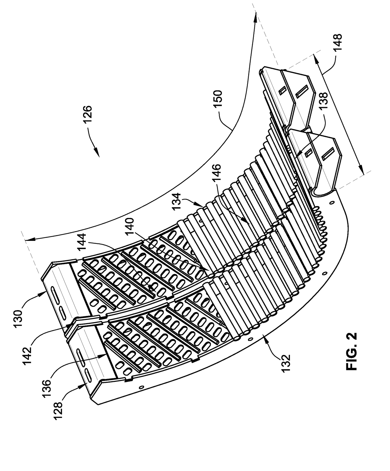
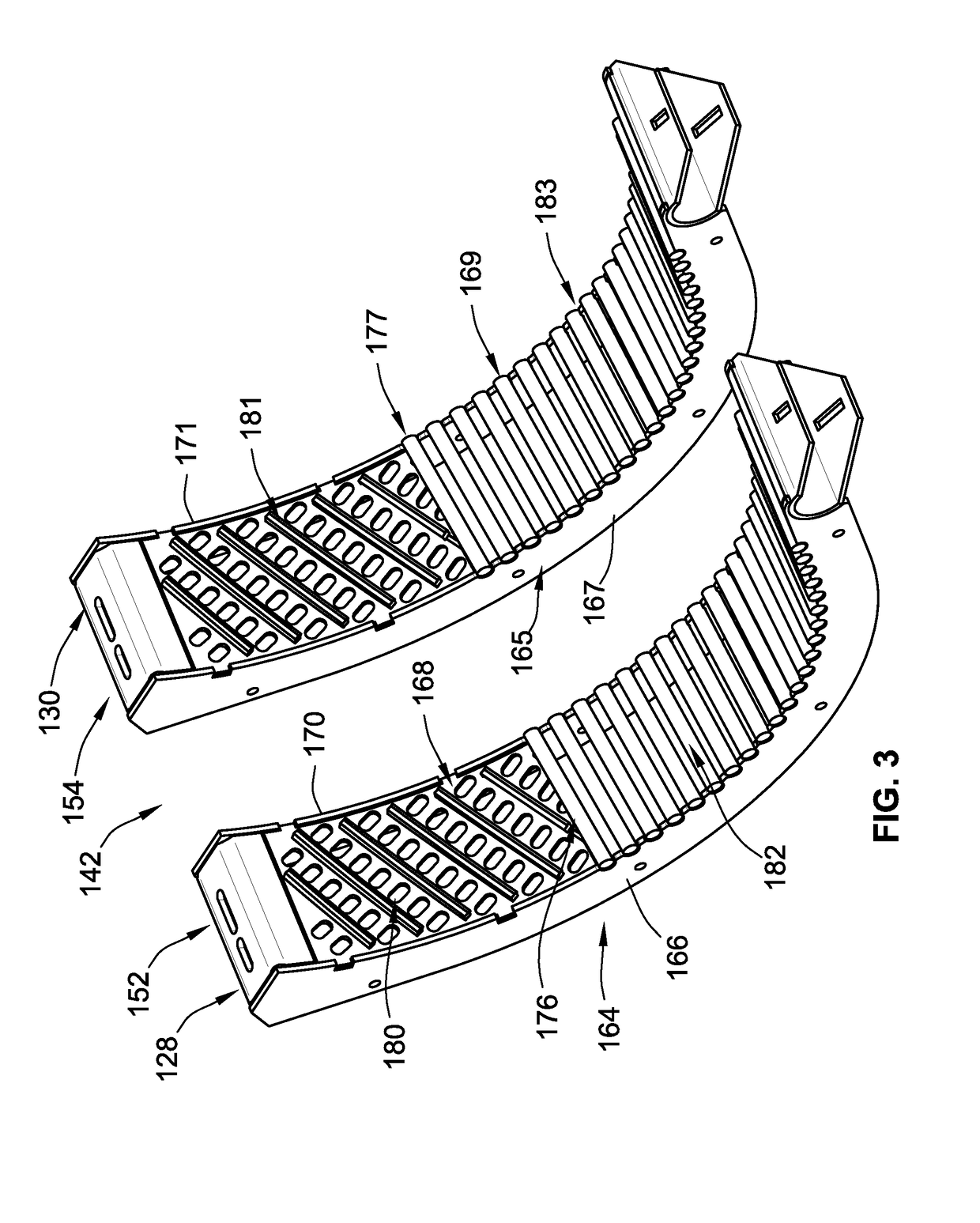
[0122]The present embodiments provide for various improvements over prior art concave sections of a full width such as those for example of FIG. 33. FIG. 33 was discussed briefly above and illustrates a concave section that has a crop engagement face that cannot be changed. It can only provide one fixed threshing profile or separation profile or combination. It is significantly heavier and wider than the embodiments described herein which makes it (FIG. 33) much more difficult to handle and install. Further, it does not provide the flexibility discussed above of, of the embodiments of the partial width concave sections 126 or 128 that allow for changing out the crop engagement face such that anywhere from one to four different profiles could be present and easily interchanged by simply removing a one of or both partial width concave sections 126, 128 to provide the desired degree of threshing or separation or both. Indeed, the widths and weights and profiles of the concave sections ...
embodiment 1000
[0124]FIG. 11 illustrates embodiment 1000 of a rotator cage section. Rotator cage section 1000 is configured for increased separation and decreased threshing with respect to FIG. 10. That is, rotor cage section 1000 includes concave assemblies 700, 800 and 900. Concave assembly 700 includes concave sections 728 and 730. Concave assembly 800 includes concave sections 828, 830. Concave assembly 900 includes concave sections 928 and 930. Here only concave section 728 includes a first thresher profile portion 780 that extends from a leading end 1056 to a trailing end 1060 of the rotator cage section 1000. The remaining sections all have separator profiles. In other words, in FIG. 10 two of the six concave sections have threshing profiles while here only one of the six concave sections has a threshing profile. Accordingly, rotor cage section 1000 is configured to have greater separation function than rotator cage 600 of FIG. 10.
[0125]FIG. 12 illustrates yet another configuration for a ro...
PUM
 Abstract
Description
Claims
Application Information