Viewing device for vehicle

Inactive Publication Date: 2019-02-07
KK TOKAI RIKA DENKI SEISAKUSHO
View PDF1 Cites 1 Cited by
  • Summary
  • Abstract
  • Description
  • Claims
  • Application Information

AI Technical Summary

Benefits of technology

[0009]In the viewing device for a vehicle of the first aspect of the present invention, the restricting member restricts rotation of the rotation member, and the visual recognition portion assists visual recognition by a vehicle occupant. The visual recognition portion is swung by drive force acting on the rotation member.
[0010]Note that the biasing portion causes biasing force in the rotation direction of the rotation member to act on one from out of the rotation member or the restricting member. This enables deformation of the biasing portion in the rotation direction of the rotation member through the rotation member to be suppressed, even when drive force acts on the rotation member.
[0011]In the viewing device for vehicle of the second aspect of the present invention, the biasing portion causes biasing force to act on the restricting member. This enables the rotation member to be suppressed from moving when the restriction on rotation of the rotation member by the restri

Problems solved by technology

Note that in this automobile door mirror device, when drive force from the motor acts on the main gear and the coil spring undergoes elastic deformation through the main gear and the clutch in a rotation direction of the main gear suc

Method used


Image

  • Viewing device for vehicle
  • Viewing device for vehicle
  • Viewing device for vehicle

Examples


Example

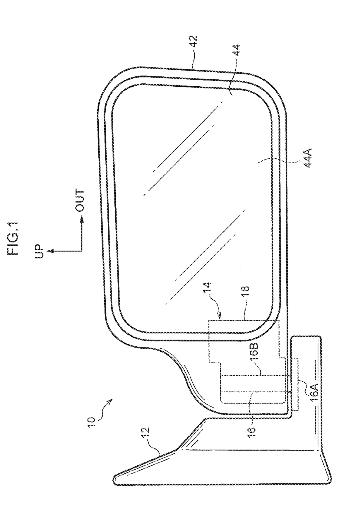
[0019]FIG. 1 is a face-on view illustrating a vehicle door mirror device 10 serving as a viewing device for vehicle according to an exemplary embodiment of the present invention, as viewed from a vehicle rear. Note that in the drawings, the arrow FR indicates a vehicle front, the arrow OUT indicates a vehicle width direction outside (a vehicle right side), and the arrow UP indicates an upper side.

[0020]The vehicle door mirror device 10 according to the present exemplary embodiment is provided to an up-down direction intermediate portion of, and a vehicle front side end of, a side door serving as a vehicle door (in particular a front side door), and is disposed on the outside of the vehicle.

[0021]As illustrated in FIG. 1, the vehicle door mirror device 10 includes a stay 12 serving as an installation member. The vehicle door mirror device 10 is installed to the side door by fixing a vehicle width direction inside end of the stay 12 to the side door (the vehicle body side).

[0022]A sto...


PUM


Abstract

In a stowing mechanism-of a vehicle door mirror device, a clutch plate restricts rotation of a gear plate, and a motor is driven such that rotation force acts on the gear plate and a swing body is rotated. Note that a coil spring biases the clutch plate in the direction of rotation. This enables deformation of the coil spring to be suppressed, even when rotation force is input to the coil spring from the gear plate through the clutch plate when the motor is driven.

Description

TECHNICAL FIELD[0001]The present invention relates to a viewing device for vehicle in which a visual recognition portion assists the visual recognition of a vehicle occupant.BACKGROUND ART[0002]In an automobile door mirror device disclosed in Japanese Patent Application Laid-Open (JP-A) No. 2000-85470, a coil spring biases a clutch toward a main gear, the clutch restricts rotation of the main gear, and drive force from a motor acts on the main gear to swing a mirror.[0003]Note that in this automobile door mirror device, when drive force from the motor acts on the main gear and the coil spring undergoes elastic deformation through the main gear and the clutch in a rotation direction of the main gear such that drive force from the motor no longer acts on the main gear, the coil spring undergoes elastic recovery, and there is a possibility that, for example, a scraping noise (abnormal noise) of the main gear against the clutch occurs.SUMMARY OF INVENTIONTechnical Problem[0004]In consid...

Claims


Application Information

Patent Timeline
IPC IPC(8): B60R1/07
CPCB60R1/07B60R1/074
Inventor YOSHIDA, SHIGEKI
Owner KK TOKAI RIKA DENKI SEISAKUSHO
Why Eureka
Try Eureka