

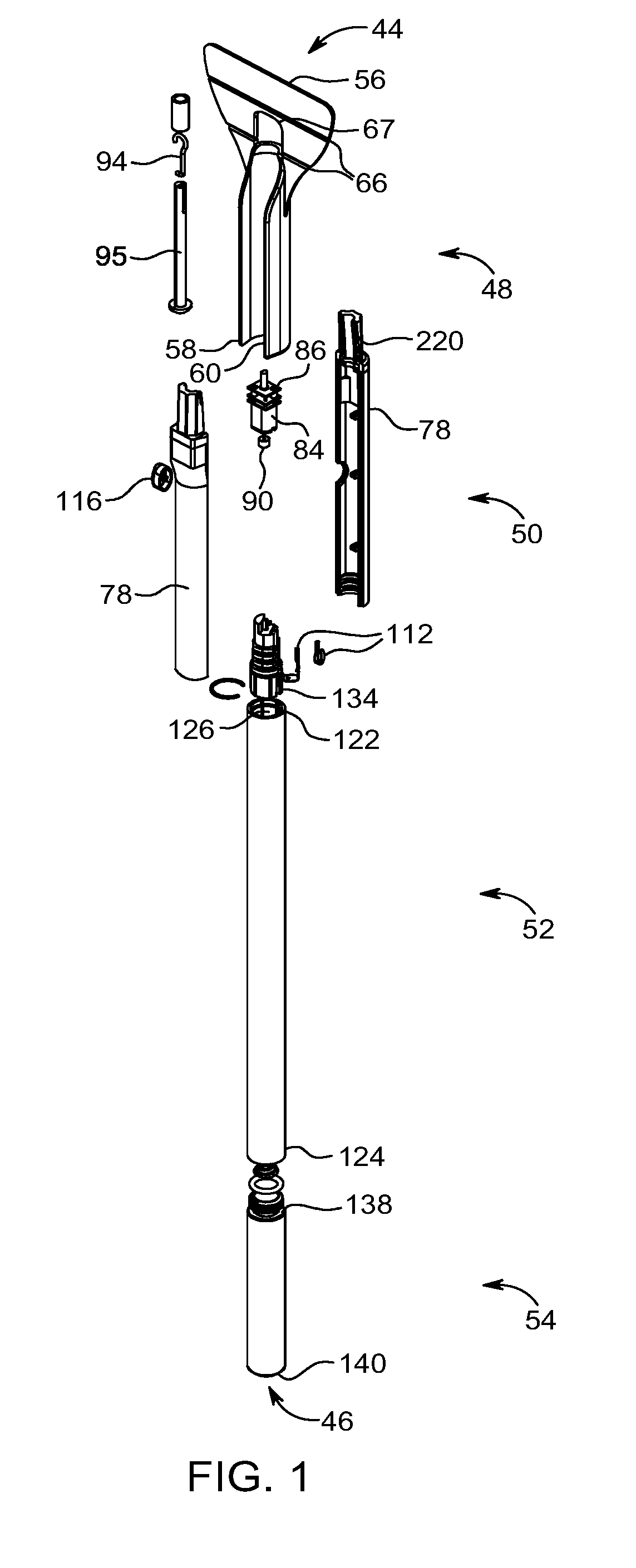
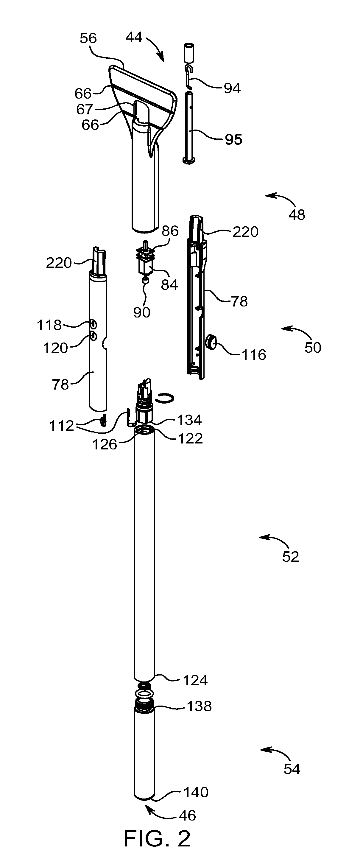
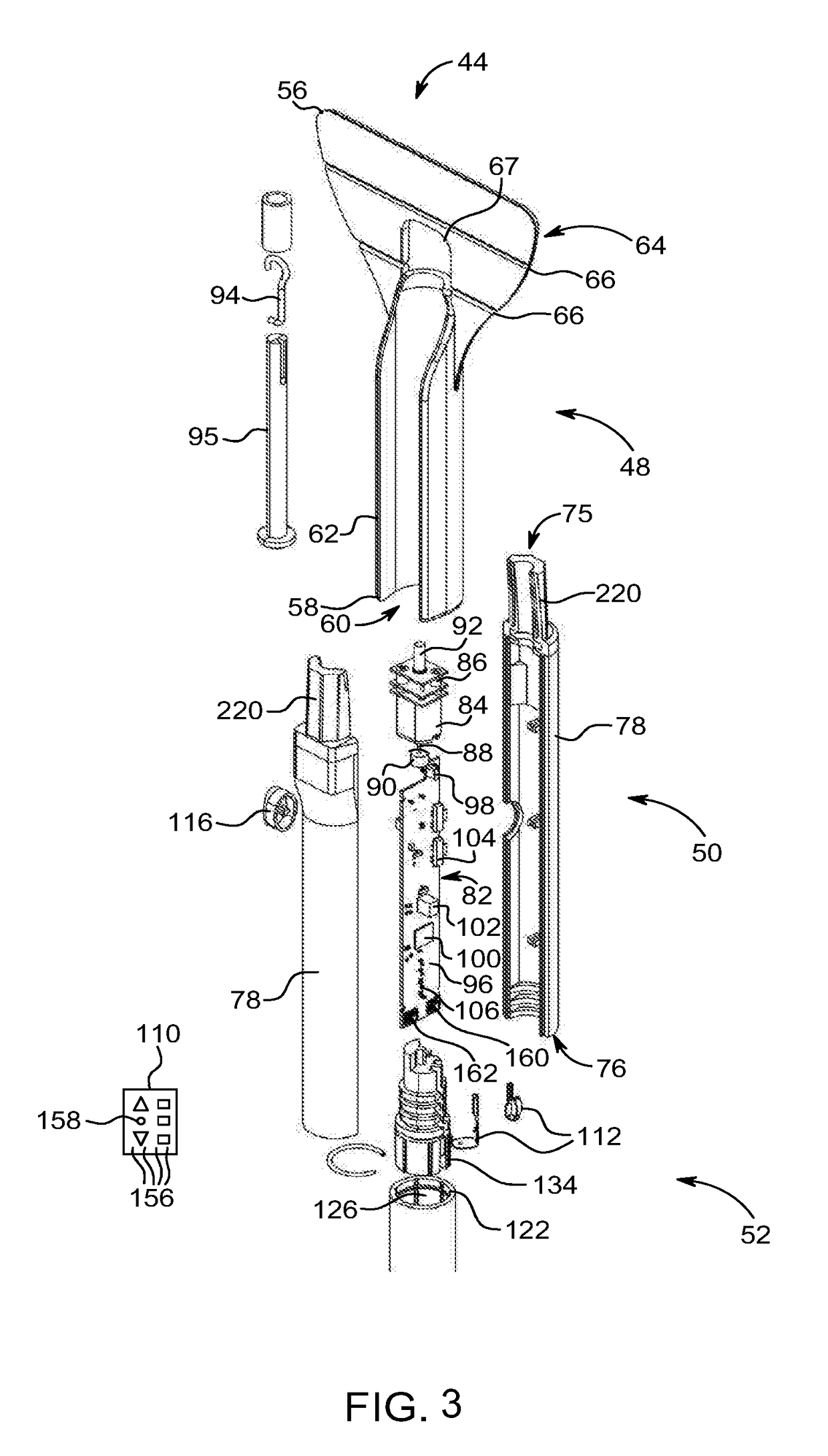
Remote controlled motorized wand for controlling blinds
a motorized wand and blind technology, applied in the field of blinds, can solve problems such as excessive nois
- Summary
- Abstract
- Description
- Claims
- Application Information
AI Technical Summary
Benefits of technology
Problems solved by technology
Method used
Image

Examples
first example
[0218]As a first example of the operation of the incremental movement system presented herein, a motorized window covering 230 that is a Venetian shade or horizontal blind 12 is presented. A user presses a button on remote 110 to move the slats 18 from a fully closed position (the start position 236) to a fully opened position or level position (the end position 238). Upon pressing the button on remote 110 a wireless movement command is transmitted which is received by antenna 106. This signal is received by motor controller 82 and motor controller 82 interprets the command signal as a standard movement command 232 (because the user likely pressed the button to open the slats 18 because they want to see outside or let the light into the building). In response, motor controller 82 supplies power to motor 84 in a continuous manner or a generally continuous manner causing the shade material 16 to move from the start position 236 to the end position 238 in a relatively rapid fashion. In...
second example
[0221]As a second example of the operation of the incremental movement system presented herein, a motorized window covering 230 that is a roller shade or honeycomb shade is presented. A user presses a button on remote 110 to move the shade material 16 from a fully closed position (the start position 236) to a fully opened position or level position (the end position 238). Upon pressing the button on remote 110 a wireless movement command is transmitted which is received by antenna 106. This signal is received by motor controller 82 and motor controller 82 interprets the command signal as a standard movement command 232 (because the user likely pressed the button to open the shade material 16 because they want to see outside or let the light into the building). In response, motor controller 82 supplies power to motor 84 in a continuous manner or a generally continuous manner causing the shade material 16 to move from the start position 236 to the end position 238 in a relatively rapi...
PUM
 Abstract
Description
Claims
Application Information