Shielding unit for wireless power transmission module and wireless power transmission module including same

Active Publication Date: 2019-02-07
AMOSENSE
View PDF0 Cites 11 Cited by
  • Summary
  • Abstract
  • Description
  • Claims
  • Application Information

AI Technical Summary

Benefits of technology

The present invention provides a shielding unit for a wireless power transfer module to increase the efficiency of the antenna. This is achieved by positioning a magnetic body away from the magnetic field shielding sheet to reduce the movement of the time-invariant magnetic field towards the shielding sheet. This reduces the amount of magnetic field that enters the shielding sheet, which prevents the sheet from becoming magnetized and improves charging efficiency. Additionally, the thickness of the magnetic body can be increased without increasing the overall thickness of the wireless power transfer module, making it suitable for thin portable terminals.

Problems solved by technology

Accordingly, when the wireless power transmission module and the wireless power reception module are close to each other, the magnetic field shielding sheet is partially or wholly magnetized by a time-invariant magnetic field, thereby deteriorating the performance of the shielding sheet or failing to function as the shielding sheet.
Accordingly, in the case of an antenna disposed at a position corresponding to the area A magnetized by the time-invariant magnetic field, there is a problem that the performance is deteriorated or the normal operation is impossible and then the transmission efficiency is lowered.
In this manner, as in the PMA standard method described above, a part or all of the magnetic field shielding sheet is magnetized by the time-invariant magnetic field generated from the permanent magnet, thereby deteriorating the performance of the shielding sheet or failing to the function as the shielding sheet smoothly.
Therefore, in the case of an antenna disposed at a position corresponding to an area magnetized by the time-invariant magnetic field, there is a problem that the performance is lowered or the normal operation is impossible and then the transmission efficiency is lowered.

Method used


Image

  • Shielding unit for wireless power transmission module and wireless power transmission module including same
  • Shielding unit for wireless power transmission module and wireless power transmission module including same
  • Shielding unit for wireless power transmission module and wireless power transmission module including same

Examples


Embodiment Construction

[0038]The above and other objects, features, and advantages of the present invention can be appreciated by the following description and will be understood more clearly by embodiment of the present invention. In addition, it will be appreciated that the objects and advantages of the present invention will be easily realized by means shown in the appended patent claims, and combinations thereof. Accordingly, the technical spirit of the present invention can be easily implemented by an ordinary skill in the art.

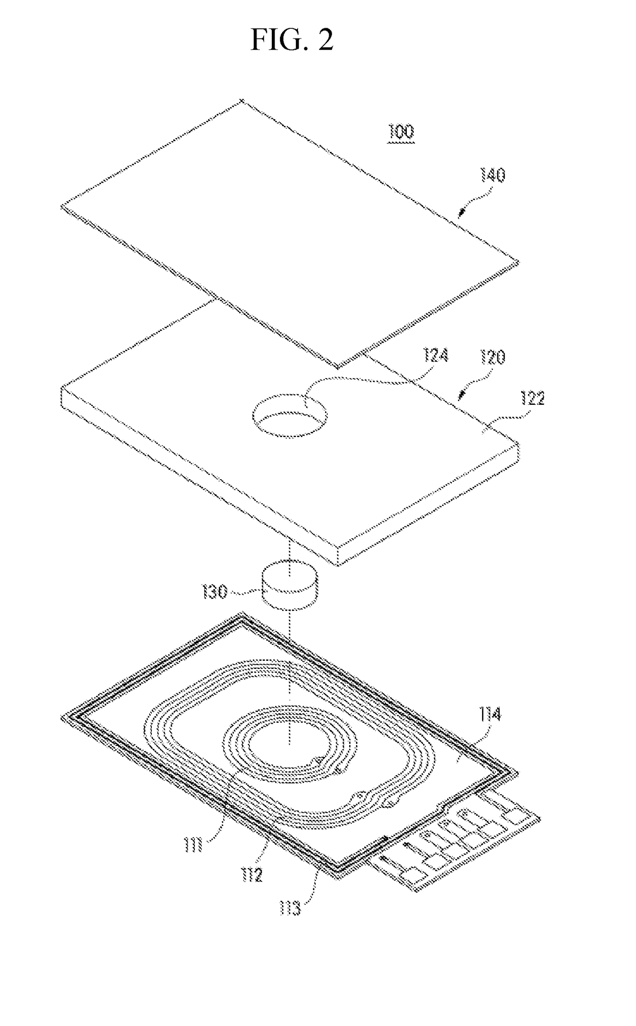
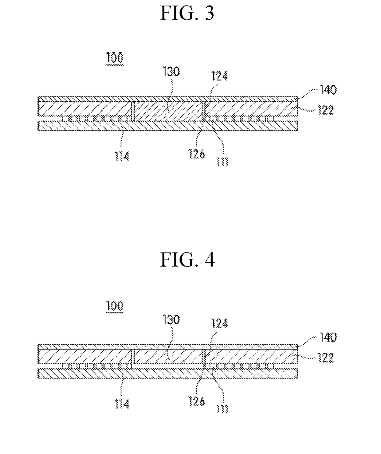
[0039]The wireless power transfer module 100 or 200 according to an embodiment of the present invention may include at least one antenna 111, 112, or 113, a shielding unit 120, and a magnetic body 130 as shown in FIGS. 2 to 5.

[0040]As shown in FIG. 9, the wireless power transfer module 100 or 200 which is used as the wireless power reception module may be built in a portable terminal 90 such as a smart phone and are electrically connected to a battery to receive wireless power ...


PUM


Abstract

A shielding unit for a wireless power transfer module and the wireless power transfer module including the same are provided. The shielding unit for the wireless power transfer module according to an embodiment of the present invention comprises a magnetic field shielding sheet for shielding a magnetic field generated in a predetermined frequency band and condensing the same in a desired direction, and a magnetic body receiving portion which is formed through the magnetic field shielding sheet such that a magnetic body for including magnetic force lines generated from a permanent magnet can be inserted therein, wherein the magnetic body receiving portion is arranged to have a relatively larger size than the magnetic body.

Description

CROSS-REFERENCE TO RELATED APPLICATION[0001]This application claims the priority benefit of Korean Patent Application No. 10-2016-0014470 on Feb. 4, 2016 in the Korean Intellectual Property Office, the disclosure of which is incorporated herein by reference.BACKGROUND OF THE DISCLOSUREField of the Disclosure[0002]The present invention relates to wireless charging of a portable terminal and the like, and more particularly, to a shielding unit for a wireless power transfer module and the wireless power transfer module including the same, which can be applied to a wireless power transfer method employing a permanent magnet.Description of the Related Art[0003]A portable terminal has a wireless charging function for wirelessly charging a built-in battery. The wireless charging function is performed by a wireless power reception module built in the portable terminal and a wireless power transmission module for supplying power to the wireless power reception module.[0004]In addition, the w...

Claims


Application Information

Patent Timeline
IPC IPC(8): H02J50/70H02J50/10H01F27/36H05K9/00H04B5/00
CPCH02J50/70H02J50/10H01F27/365H05K9/00H04B5/0037H04B5/0081H01F38/14H01F27/36H01F27/366H04B5/26H04B5/79
Inventor JANG, KIL JAELEE, DONG HOONKIM, KI CHULPARK, JONG HO
Owner AMOSENSE
Why Eureka
Try Eureka