Vehicle mounting device for surveillance equipment

a technology for surveillance equipment and mounting devices, which is applied in the direction of optical radiation measurement, instruments, and using reradiation, etc., can solve the problems of revealing a position to enemies, inability to freely realize angle variations, and insufficient vibration resistance against shaking generated during vehicle running, etc., to achieve convenient mounting, superior operability, and stable security

Active Publication Date: 2019-02-14
SEHWA MOTOR
View PDF8 Cites 3 Cited by
  • Summary
  • Abstract
  • Description
  • Claims
  • Application Information

AI Technical Summary

Benefits of technology

[0011]According to the present invention, the following effects can be provided: the thermal observation device and radar can be mountable on the four-wheel drive vehicle used on rough mountainous roads; and the thermal observation device and radar can be easily mounted on the vehicle; the surveillance range can be stably secured; and superior operability can be provided through easy attachment and detachment.
[0012]Furthermore, mobile surveillance equipment according to the present invention provides movement to a desired place upon surveillance work and thus can reduce exposure to enemies. Thus, a wide surveillance range effect can be achieved by using a single equipment, leading to potentially valuable use in many other applications.

Problems solved by technology

The carrying out of surveillance work using surveillance equipment that is mounted in a fixed location poses a danger of revealing a position to enemies, and thus the location must be kept hidden upon an infiltration operation.
However, in the related art, vibration resistance against shaking due to impact generated during vehicle running may be inadequate in a country like Korea that consists of mountainous terrain and many roads and small roads with steep slopes.
Additionally, large angle variation is required in mountainous terrain, but this angle variation may not be freely realized.

Method used


Image

  • Vehicle mounting device for surveillance equipment
  • Vehicle mounting device for surveillance equipment
  • Vehicle mounting device for surveillance equipment

Examples


embodiment 1

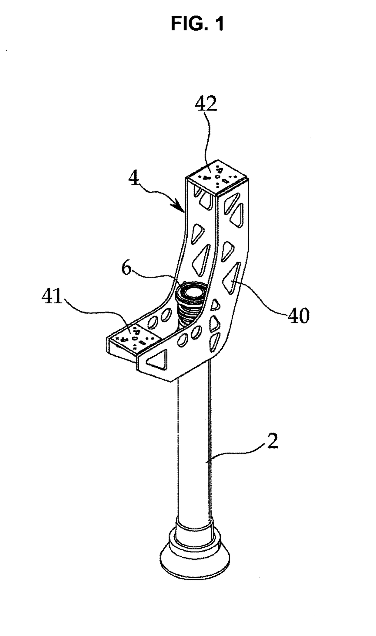
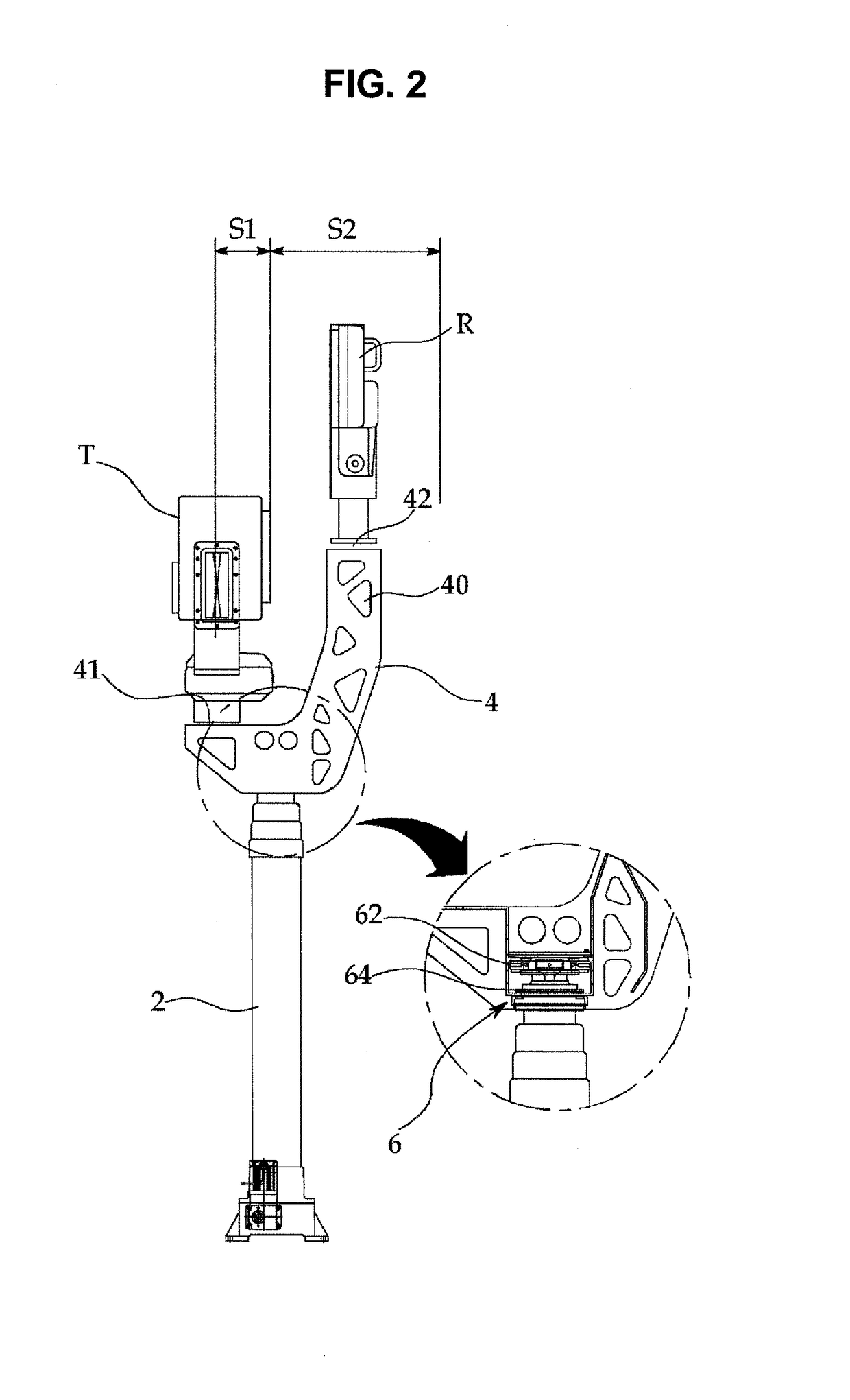
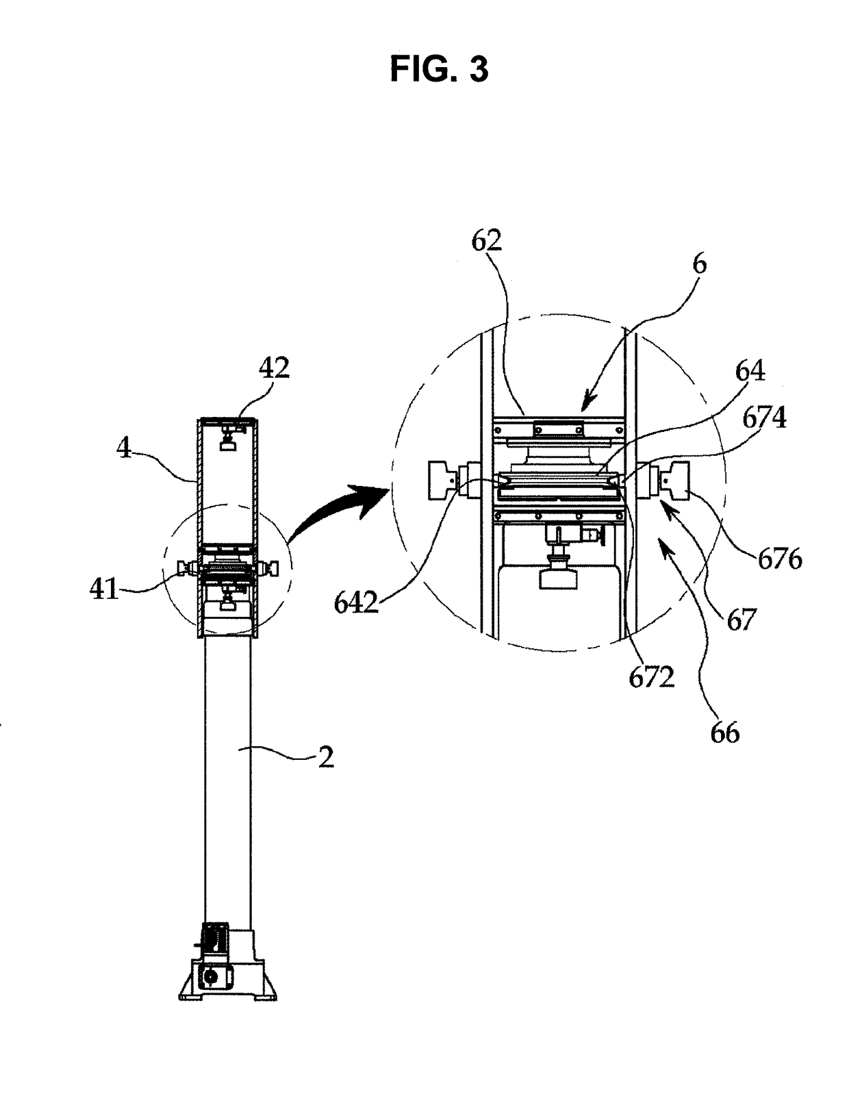
[0026]In the accompanying drawings, FIG. 1 is a perspective view showing a surveillance equipment mounting device for a vehicle according to a first embodiment of the present invention, FIG. 2 is a front view showing the surveillance equipment mounting device for a vehicle according to the first embodiment of the present invention, FIG. 3 is a side view showing the surveillance equipment mounting device for a vehicle according to the first embodiment of the present invention, FIG. 4 is an enlarged plan view showing a braking operation member in the surveillance equipment mounting device for a vehicle according to the first embodiment of the present invention, FIG. 5 is an enlarged sectional view showing the braking operation member in the surveillance equipment mounting device for a vehicle according to the first embodiment of the present invention, FIG. 6 is an enlarged exploded perspective view showing the braking operation member in the surveillance equipment mounting device for ...

embodiment 2

[0059]FIG. 8 is an exploded perspective view showing a surveillance equipment mounting device for a vehicle according to a second embodiment of the present invention, FIG. 9 is an enlarged exploded perspective view showing a rotary member in the surveillance equipment mounting device for a vehicle according to the second embodiment of the present invention, and FIG. 10 is an assembled front view showing the surveillance equipment mounting device for a vehicle according to the second embodiment of the present invention.

[0060]As shown in FIGS. 8 to 10, a surveillance equipment mounting device for a vehicle according to a second embodiment of the present invention includes: a pillar 2 vertically provided on a floor of a vehicle; and a support member 4 having a substantially arced shape and horizontally provided on a top end of the pillar 2.

[0061]The pillar 2 is configured with multiple pillar rods fitted to each other in a telescopic manner such that a lower end thereof is fixedly moun...


PUM


Abstract

The present invention relates to a surveillance equipment mounting device for a vehicle, the device including: a pillar vertically provided on a floor of a vehicle; and a support member horizontally provided on a top end of the pillar and having a substantially ‘’shape, wherein the support member is configured such that a first side section is shorter than a second side section with respect to the top end of the pillar, the first side section has an end provided with a first mounting part on which the equipment is mounted, and the second side section has an end provided with a second mounting part, the first mounting part being provided at a position lower than the second mounting part.

Description

TECHNICAL FIELD[0001]The present invention relates generally to a surveillance equipment mounting device for a vehicle. More particularly, the present invention relates to a surveillance equipment mounting device for a vehicle, wherein a thermal observation device and radar are easily mounted on a vehicle, a surveillance range is stably secured, and superior operability is provided through easy attachment and detachment.BACKGROUND ART[0002]Among vehicle-mounted surveillance equipment, a thermal observation device (TOD) is a device that detects infrared rays of an object and converts the same into a video image. It is mainly used for identification of location and dynamics of moving persons and targets during night, and for detection of hidden places.[0003]Furthermore, among the vehicle-mounted surveillance equipment, long-range ground surveillance radar is used to detect moving persons and vehicles within a range of 20 km. The surveillance equipment is mounted in a vehicle for carry...

Claims


Application Information

Patent Timeline
Patent Type & Authority Applications(United States)
IPC IPC(8): B60R11/00B62D27/06G01J5/00G01S13/89
CPCB60R11/00B62D27/06G01J5/0025G01S13/89B60R2011/0029B60R2011/0052B60R2011/0066B60R2011/0082G01J2005/0077B60R2300/107B60R2300/301B60R2011/0085B60R2011/0092G01S13/86G01S13/0218H01Q1/18H01Q1/1228H01Q1/3291H01Q1/3233F16M13/02F16M11/08F16M11/18F16M11/28G01J5/0022G01J5/047G01S7/027G01J5/00F16M11/20
Inventor KIM, DONG GEUNKANG, SEONG JOO
Owner SEHWA MOTOR
Why Eureka
Try Eureka