Method and device for testing a detection sensor for a motor vehicle

a detection sensor and motor vehicle technology, applied in powerline communications applications, instruments, transmission/receiving by adding signal to wave, etc., can solve problems such as major drawbacks, and achieve the effect of simple, reliable and effectiv

Active Publication Date: 2019-02-28
CONTINENTAL AUTOMOTIVE FRANCE +1
View PDF3 Cites 1 Cited by
  • Summary
  • Abstract
  • Description
  • Claims
  • Application Information

AI Technical Summary

Benefits of technology

[0016]The aim of an aspect of the invention is to at least partly rectify these drawbacks by proposing a simple, reliable and effective solution for testing detection sensors at high frequencies.

Problems solved by technology

In this case, the sensor is not able to determine whether binary test information is contained in the test signal, thereby preventing the test device from collecting the samples, and therefore constituting a major drawback.

Method used


Image

  • Method and device for testing a detection sensor for a motor vehicle
  • Method and device for testing a detection sensor for a motor vehicle
  • Method and device for testing a detection sensor for a motor vehicle

Examples


Embodiment Construction

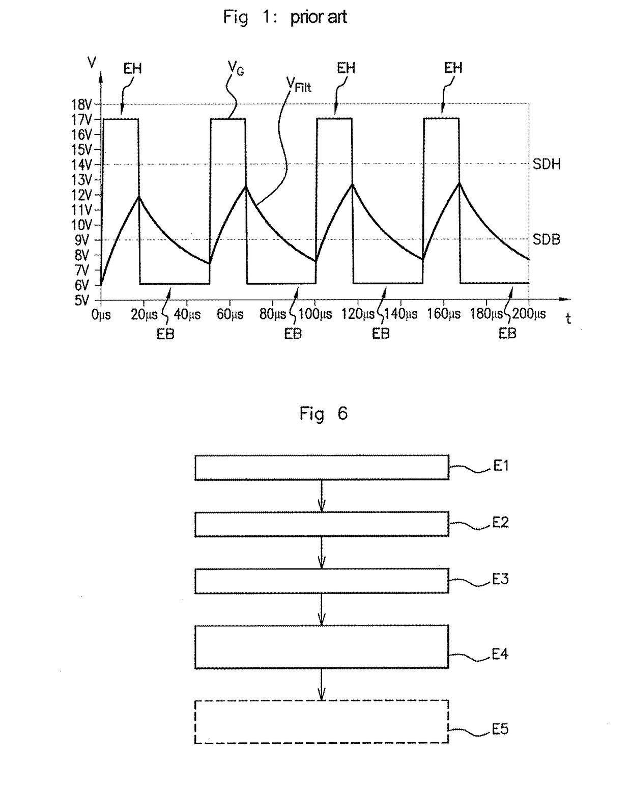
[0043]The test system according to an aspect of the invention makes it possible to test a sensor for detecting a target fixed to a drive shaft for a motor vehicle, in particular by allowing the collection of data relating to the output signal delivered by said sensor, such as for example the value of the magnetic field measured by the sensor.

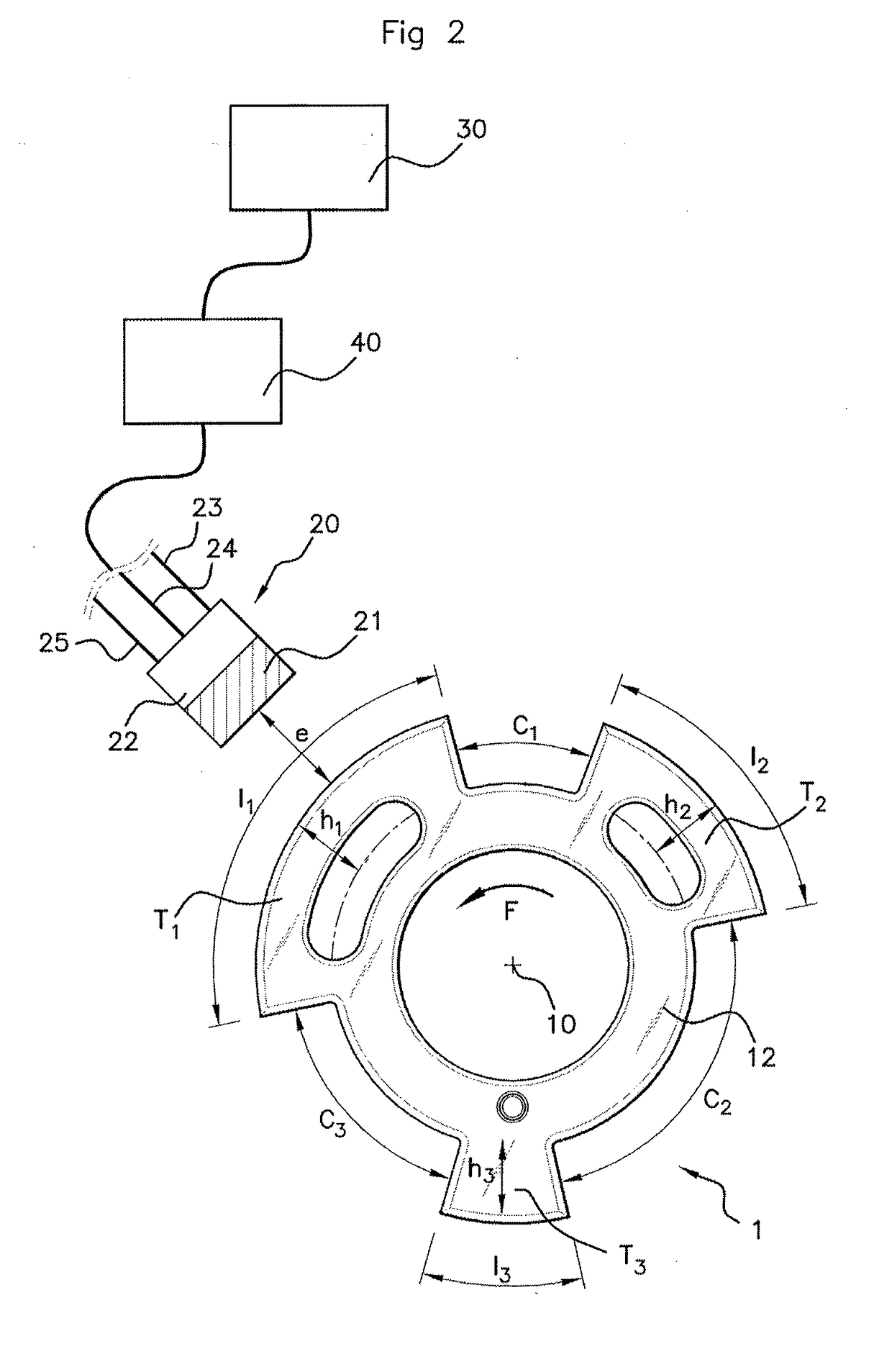
[0044]To this end, with reference to FIG. 2, the system 1 comprises a drive shaft 10, on which a target 12 is installed, a detection sensor 20 positioned facing said target 12, a generation module 30 and an amplification module 40.

[0045]The tests may be carried out using a detection sensor 20 installed on a test bench facing a target 12 on a test drive shaft 10, allowing simulation of the operation of a motor vehicle drive shaft, or else using a detection sensor 20 already installed in a motor vehicle. In the latter case, the drive shaft 10 may be for example a crankshaft, a camshaft or a transmission shaft.

[0046]To perform these tests, it is ne...


PUM


Abstract

A method for testing a detection sensor positioned facing a target fixed to a drive shaft that is intended to be installed in a motor vehicle. The method includes generating a pulsed voltage test signal, amplifying the high states of the generated test signal, filtering the amplified test signal so as to obtain a voltage test signal having high states the voltage of which is higher than a predetermined high-state detection threshold and low states the voltage of which is lower than a predetermined low-state detection threshold, and detecting the high states and the low states of the filtered test signal in order to test the sensor.

Description

CROSS REFERENCE TO RELATED APPLICATIONS[0001]This application is the U.S. National Phase Application of PCT International Application No. PCT / EP2016 / 002150, filed Dec. 21, 2016, which claims priority to French Patent Application No. 1650738, filed Jan. 29, 2016, the contents of such applications being incorporated by reference herein.FIELD OF THE INVENTION[0002]The present invention relates to the field of testing detection sensors for motor vehicles, and pertains more particularly to a method and to a system for testing a sensor for detecting a target fixed to a drive shaft of a motor vehicle.[0003]The invention is applicable in particular in the detection of a target fixed to a crankshaft, a camshaft or a transmission shaft of a motor vehicle.BACKGROUND OF THE INVENTION[0004]In a motor vehicle, it is known to use what are termed ‘detection’ sensors to determine the position of a drive shaft or else its rotational speed. Such a shaft may be for example a crankshaft, a camshaft or a...

Claims


Application Information

Patent Timeline
Patent Type & Authority Applications(United States)
IPC IPC(8): G01P21/02G01D5/14G01P3/489G01D18/00
CPCG01P21/02G01D5/145G01P3/489G01D18/00G01D3/08H04B2203/5416H04B2203/5458H04B2203/547
Inventor MIRASSOU, DAVID
Owner CONTINENTAL AUTOMOTIVE FRANCE
Why Eureka
Try Eureka