Device for detecting a parasitic metallic object in the emission zone of a device for recharging a user apparatus for an automotive vehicle and associated detection method
What is AI technical title?
AI technical title is built by Patsnap AI team. It summarizes the technical point description of the patent document.
a technology for detecting parasitic metallic objects and induction devices, which is applied in the direction of reradiation, instruments, transportation and packaging, etc., can solve the problems of significant drawbacks, significant temperature rises, and user burns, and achieve simple, reliable and effective effects
Active Publication Date: 2019-04-23
CONTINENTAL AUTOMOTIVE FRANCE +1
View PDF10 Cites 0 Cited by
Summary
Abstract
Description
Claims
Application Information
AI Technical Summary
This helps you quickly interpret patents by identifying the three key elements:
Problems solved by technology
Method used
Benefits of technology
Benefits of technology
The patent aims to solve the problem of detecting objects that can interfere with the charging of devices. The invention proposes a simple and reliable solution to reliably identify these objects and prevent them from causing damage or malfunctions. The technical effect of the invention is to improve the safety and reliability of recharging devices.
Problems solved by technology
Indeed, the generation of an electromagnetic field on a metallic object, for example of coin type, can lead to a significant rise in its temperature, for example greater than 80° C., and this may present risks of burns to the user.
Such a danger can thus arise when a user apparatus and a parasitic object are present simultaneously in the emission zone during recharging of the user apparatus, thus presenting a significant drawback.
This solution presents drawbacks however.
However, in the case where the emitting coil and the receiving coil are not aligned, the difference between the power emitted and the power received is greater than the predetermined threshold mentioned previously so that the management module of the device may incorrectly deduce therefrom that a parasitic object is present in the emission zone of the device, thus presenting a significant drawback.
This detection method is therefore not robust, and does not allow reliable detection since it is not possible to fix a unique predetermined detection threshold in order to detect a metallic parasitic object for all types of user apparatus inclusive.
Method used
Image
Click on the blue label to locate the original text in one second.
Reading with bidirectional positioning of images and text.
Examples
first embodiment
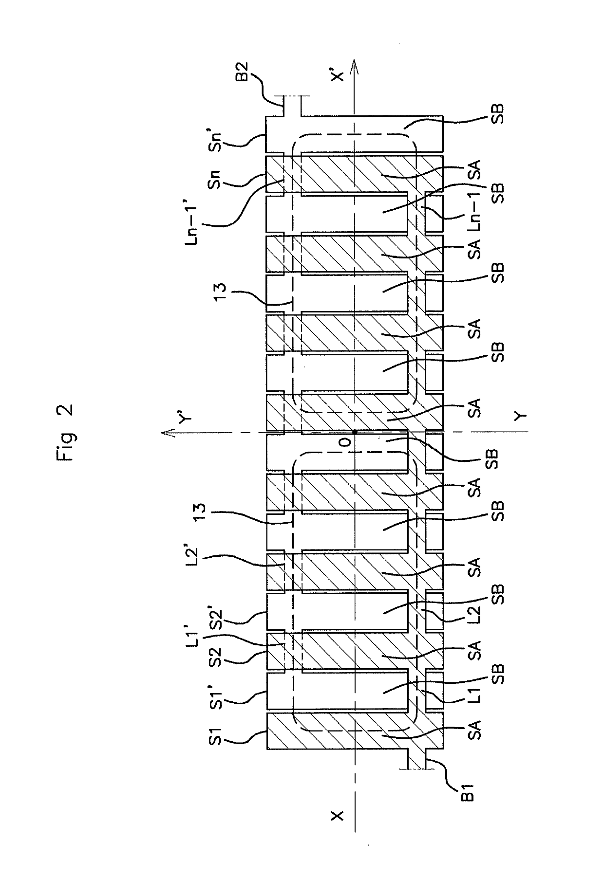
[0089]In a first embodiment, the two parallel planes P1, P2 are distinct and mutually spaced apart by a distance. The distance may for example be of the order of a millimeter.
second embodiment
[0090]In a second embodiment, the two parallel planes P1, P2 are merged as one.
[0091]All the segments S1, S2 . . . Sn, S1′, S2′ . . . Sn′ of the two coils B1, B2 are coplanar. The links L1, L2 . . . Ln−1, L1′, L2′ . . . Ln−1′ of each coil B1, B2 overlap the segments S1, S2 . . . Sn, S1′, S2′ . . . Sn′ of the other coil either from below or from above.
[0092]For example, the links L1, L2 . . . Ln of the coil B1 overlap the segments S1′, S2′ . . . Sn′ of the coil B2 from below so as to connect the segments S1, S2 . . . Sn of the coil B1 together.
[0093]The segments S1, S2 . . . Sn, S1′, S2 . . . Sn′ are of smaller dimensions than the dimensions of the emitting coil 13. Preferentially, a number of segments S1, S2 . . . Sn, S1′, S2′ . . . Sn′ is proportional to the number of emitting coils 13. For example, the number of segments S1, S2 . . . Sn, S1′, S2′ . . . Sn′ is equal to k times the number of emitting coils 13, with k≥4.
[0094]In a preferential embodiment of an aspect of the invention...
PUM
Property
Measurement
Unit
frequency
aaaaa
aaaaa
frequency
aaaaa
aaaaa
temperature
aaaaa
aaaaa
Abstract
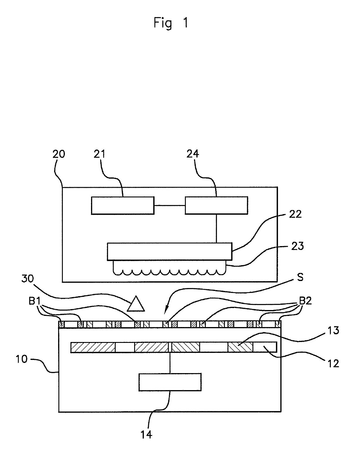
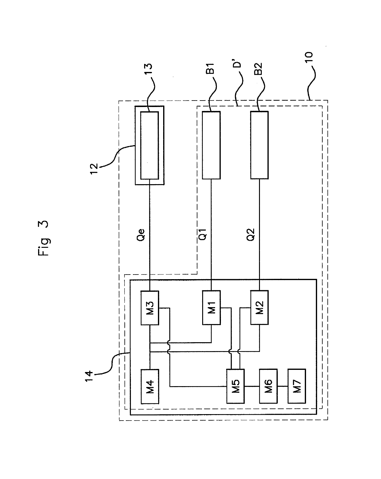
A device for detecting the presence of a parasitic metal object on a reception surface of a device for recharging a user apparatus for an automotive vehicle, the device including an antenna of the emitting coil type and: at least two identical passive detection coils, situated between the emitting coil and the reception surface; a determiner for determining the quality factor across the terminals of the two coils, and of the emitting coil; a controller; a storage device for storing the quality factors at predetermined instances; a calculator for calculating ratios between the stored quality factors, or between values of the quality factors stored at different predetermined instances; a comparator for comparing between the ratios in order to detect the presence of an interfering metal object on the reception surface.
Description
CROSS REFERENCE TO RELATED APPLICATIONS[0001]This application is the U.S. National Phase Application of PCT / EP2016 / 001826, filed Nov. 3, 2016, which claims priority to French Patent Application No. 1560669, filed Nov. 6, 2015, the contents of such applications being incorporated by reference herein.FIELD OF THE INVENTION[0002]The invention pertains to the field of the recharging with energy by induction of a user apparatus in an automotive vehicle and relates more specifically to a method and a device for detecting a parasitic metallic object in the emission zone of an induction-based recharging device of a user apparatus in an automotive vehicle.BACKGROUND OF THE INVENTION[0003]Nowadays, certain automotive vehicles are provided with a device allowing the recharging by induction of a battery of a user apparatus such as, for example, a mobile phone. The term “battery” is understood to mean in the present document an electrical energy storage unit for powering the user apparatus.[0004...
Claims
Application Information
Patent Timeline
Application Date:The date an application was filed.
Publication Date:The date a patent or application was officially published.
First Publication Date:The earliest publication date of a patent with the same application number.
Issue Date:Publication date of the patent grant document.
PCT Entry Date:The Entry date of PCT National Phase.
Estimated Expiry Date:The statutory expiry date of a patent right according to the Patent Law, and it is the longest term of protection that the patent right can achieve without the termination of the patent right due to other reasons(Term extension factor has been taken into account ).
Invalid Date:Actual expiry date is based on effective date or publication date of legal transaction data of invalid patent.

