Power amplification device

a power amplification and power technology, applied in the field of power electronics, can solve the problems of difficult adjustment of the triggered power amplification device, significant limitation of the use of an external current generator to deliver a pulse to the triggering electrode, and relative unreliability

Active Publication Date: 2019-05-16
ENE29 S AR L
View PDF0 Cites 0 Cited by
  • Summary
  • Abstract
  • Description
  • Claims
  • Application Information

AI Technical Summary

Benefits of technology

[0008]The purpose of the present invention is to overcome, at least partially, these disadvantages by proposing a simple, reliable and effective solution of a power amplification device not requiring complex external cabling in order to be able to be used in an embedded application, for example in a downhole for a seismic application.
[0010]The input voltage is a high voltage of which the value is greater than 1 kV, preferably between 5 and 40 kV. The power amplification device according to the invention is a self-triggered device which functions with one single input voltage and therefore one single external supply cable, which makes it possible to reduce the number of cables and does not therefore require any connector with the outside to control the triggering means nor any additional battery, the supply thereof being advantageously controlled by the second voltage. The dimensions of the power amplification device according to the invention may be advantageously reduced so as to be embedded in a casing, for example to easily lower it into a borehole. The triggering module of the device according to the invention may be used with most configurations and known types of discharge electrodes and triggering means. The device according to the invention further provides stability and precision when triggering the electric arc, regardless of the geometry of the electrodes, of the distance between the first electrode and the second electrode or of the pressure of the environment, which means the amplification device may be used longer without undergoing maintenance operations.
[0012]In a first embodiment of the device, the triggering module is configured to compare the value of the input voltage with a predetermined threshold value and to generate the activation signal when the value of the input voltage is greater than or equal to the predetermined threshold value. In this case, using a voltage criterion to trigger the electric arc makes it possible to make the device independent of time, and in particular, of the charging time of the condensers of the current generator, which powers it with the input voltage.
[0023]According to another aspect of the invention, the voltage pulse signal reaches a maximum value of around 20 kV, making it possible for the triggering means to trigger the formation of the electric arc between the first discharge electrode and the second discharge electrode.

Problems solved by technology

Such a device is of simple design, but has the disadvantage of being relatively unreliable, given that in a gaseous environment or in the vacuum, the triggering value, in reality, follows a Gaussian distribution around the desired threshold value.
However, when it is triggered by exceeding a self-priming threshold, a triggered power amplification device is difficult to adjust, which represents a first disadvantage.
Furthermore, using an external current generator to deliver a pulse to the triggering electrode has a significant limitation for an embedded use, in particular in the case of a borehole wherein it is necessary to lower both the supply cable of the triggering electrode and the high voltage supply cable of the main electrodes.
Thus, the result is a great cabling complexity, in particular to return the anode of each power amplification device to the anode of the nearby condensers, which is added to the cablings of the triggering electrode and of the main electrodes of each triggered power amplification device, which also has significant disadvantages.

Method used


Image

  • Power amplification device
  • Power amplification device

Examples


first embodiment

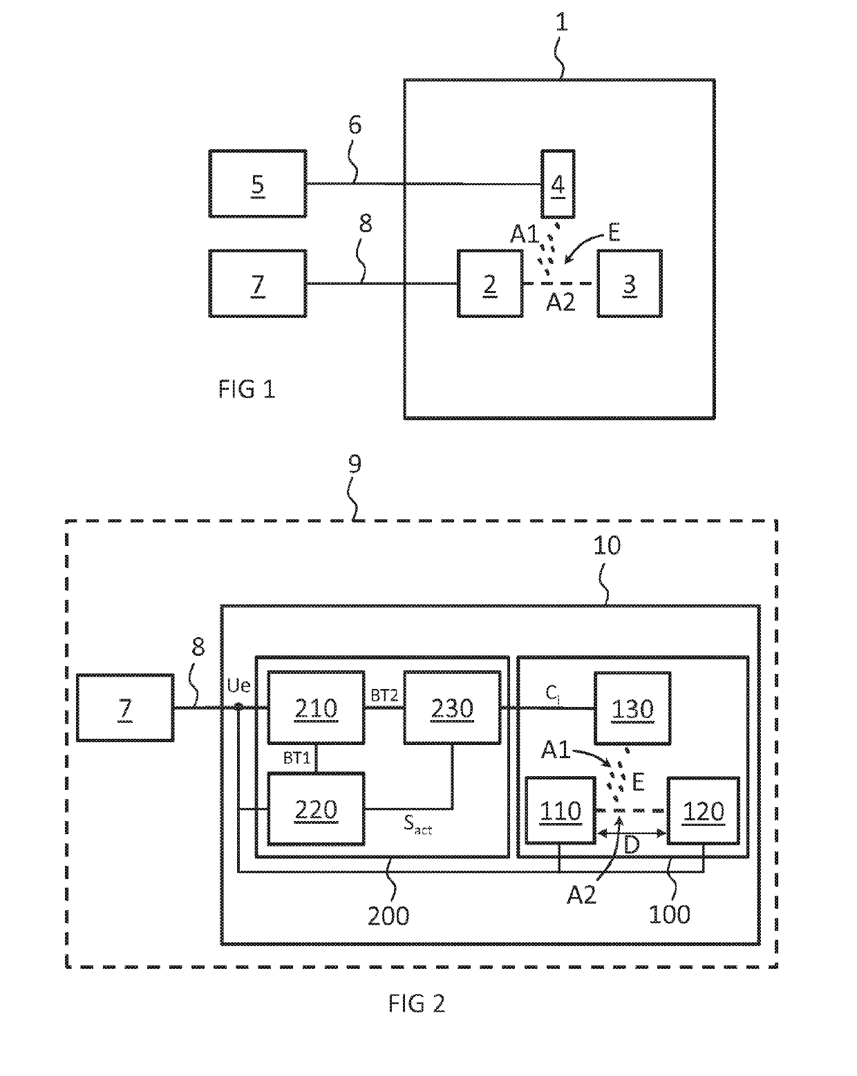
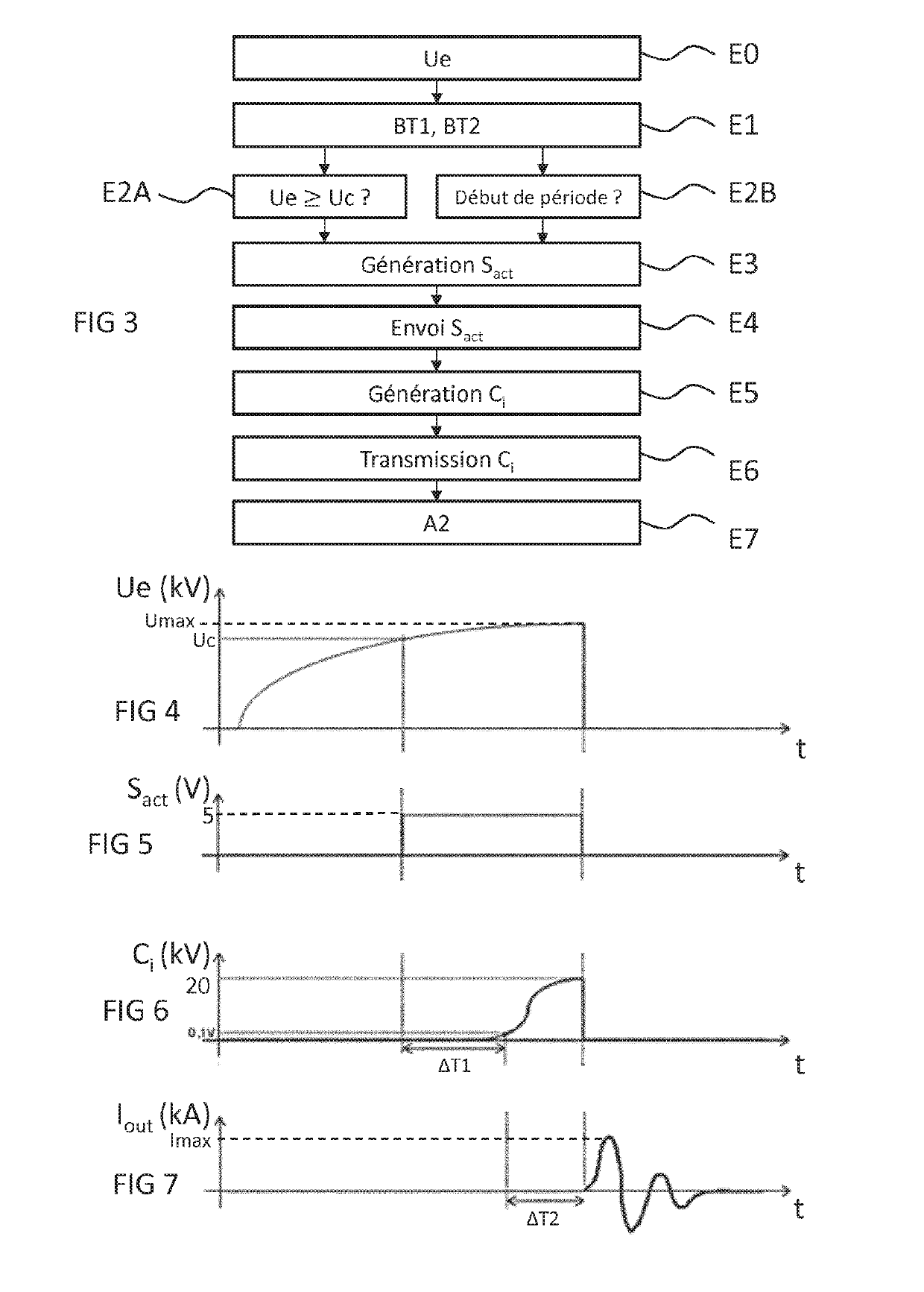
[0012]In the device, the triggering module is configured to compare the value of the input voltage with a predetermined threshold value and to generate the activation signal when the value of the input voltage is greater than or equal to the predetermined threshold value. In this case, using a voltage criterion to trigger the electric arc makes it possible to make the device independent of time, and in particular, of the charging time of the condensers of the current generator, which powers it with the input voltage.

[0013]Advantageously, in this first embodiment, the detection sub-module is configured to receive the input voltage, to compare the value of the input voltage with a predetermined threshold value and, when the value of the input voltage is greater than or equal to the predetermined threshold value, to generate the activation signal from the first supply voltage and to send said activation signal to the pulse generator.

[0014]Preferably, the delay between the detection of ...

second embodiment

[0015]In the device, the triggering module comprises a timer and is configured to generate the activation signal periodically relying on said timer.

[0016]Advantageously, in this second embodiment, the detection sub-module comprises the timer and is configured to periodically generate the activation signal from the first supply voltage and to send said activation signal to the pulse generator.

[0017]Preferably, the triggering means is presented in the form of a triggering electrode.

[0018]Preferably, the value of the first voltage is between 1 and 15V.

[0019]Advantageously, the activation signal is presented in the form of a voltage step of which the amplitude is less than 15V.

[0020]Advantageously, the value of the amplitude of the voltage step is equal to the value of the first voltage.

[0021]Advantageously also, the value of the second voltage is around several hundred Volts, preferably around 500V.

[0022]According to an aspect of the invention, the pulse command is presented in the for...


PUM


Abstract

The present invention relates to a power amplification device capable of being powered by a single input voltage and comprising a switching module comprising a first discharge electrode and a second discharge electrode. The power amplification device comprises a triggering module configured to convert the input voltage into a first supply voltage and a second supply voltage, detect an activation event, generate an activation signal from the first supply voltage when an activation event has been detected, generate a pulse command from the second supply voltage when an activation signal has been generated, and transmit the generated pulse control to the triggering means of the switching module so that it triggers the formation of an electric arc between the first discharge electrode and the second discharge electrode.

Description

TECHNICAL FIELD[0001]The present invention relates to the field of power electronics and relates more specifically to a power amplification device. Such a device is particularly applied in the scope of a bench for testing highly pressurised materials, a bench for testing a charge or in the scope of a downhole seismic application.PRIOR ART[0002]In power electronics, power amplification devices are known that make it possible to transfer, in a fraction of a second, a highly pressurised current of very high intensity between two electrodes, the polarisation voltage between the two electrodes being provided by an external supply, for example between 5 and 40 kV.[0003]Such power amplification devices are generally used in applications such as Marx generators or other highly pressurised assemblies, for example in association with condensers making it possible to store electrical energy, and to return it in the form of a highly pressurised current of very high intensity. Two categories of ...

Claims


Application Information

Patent Timeline
Patent Type & Authority Applications(United States)
IPC IPC(8): H01T2/02H01T1/22H01T15/00H03K3/537
CPCH01T2/02H01T1/22H01T15/00H03K3/537H01T1/20
Inventor DELCHAMBRE, MICHAELPECQUOIS, ROMAININNOCENTI, NICOLASGENEZ, DAVID
Owner ENE29 S AR L
Why Eureka
Try Eureka