Liquid storage device for a motor vehicle

a technology for motor vehicles and liquid storage devices, which is applied in the direction of engines, machines/engines, mechanical equipment, etc., can solve the problems of reducing engine performance, increasing the level of vehicle pollution, and losing liquid availability through uncontrolled air suction

Active Publication Date: 2022-11-15
VITESCO TECH GERMANY GMBH
View PDF17 Cites 0 Cited by
  • Summary
  • Abstract
  • Description
  • Claims
  • Application Information

AI Technical Summary

Benefits of technology

[0007]The object of the invention is therefore to remedy at least in part these drawbacks by proposing a simple, reliable and effective solution for sucking the liquid both when the reservoir is horizontal and when the reservoir is inclined over the extent of level variation allowed.
[0013]The draining mat makes it possible to easily convey the liquid to the filter by capillarity so as to avoid liquid pressure drops in the pump when the reservoir is inclined. Such conveying also makes it possible to bring the liquid permanently closer to the pump so that the heat released by the pump in operation thaws the liquid or prevents it from freezing, as the case may be. The contact portion also advantageously makes it possible to preserve the filter from debris of a larger size by constituting a pre-filter, so as to extend the service life of said filter. The mat also makes it possible to insulate the reservoir from the inside in order to reduce heat losses, in particular when a convection heating module is mounted inside the reservoir.
[0017]Advantageously, the contact between the contact portion of the mat and the filter is produced by elasticity.
[0019]Preferably, the contact surface between the contact portion of the mat and the filter is greater than one third of the total external surface of the filter capable of being in direct contact with the liquid contained in the reservoir. The mat thus increases the service life of the filter at the contact portion.
[0020]More preferably, the contact surface between the contact portion of the mat and the filter is greater than 50 cm2 in order to drain the liquid toward the filter efficiently.
[0021]In one embodiment, the mat comprises a single layer to simplify the manufacture and the cost of the device.

Problems solved by technology

A problem arises, however, when the vehicle is traveling on an inclined surface, for example on a hill.
In fact, in this case, the partially filled reservoir is also inclined so that, in some cases, the liquid may no longer be in contact with the filter, which prevents it from being sucked by the pump and from being injected, then causing losses of liquid availability by uncontrolled air suction.
In the case of a urea reservoir, a failure to inject urea solution into the exhaust gases increases the level of pollution of the vehicle, sometimes beyond regulatory standards.
In addition, failure to comply with emission standards leads to reduced engine performance, which can lead to failure thereof.
In the case of a water reservoir, a water injection fault can lead to overheating, for example in the combustion chambers or in the turbocharger, which can lead to a reduction in vehicle performance in order to preserve the engine.
In both cases, a known solution consists in detecting a liquid injection fault and ordering the engine to be switched off or its operation in a deliberately degraded mode, but this then also presents a significant drawback.
In addition, the evolution of vehicles leads more and more to reducing the height of these reservoirs to make them as flat as possible in order to reduce their size and preserve the ground clearance of the vehicle, which tends to reduce the height of liquid in the reservoir and makes it even more complex to suck the liquid by the pump on an inclined surface.

Method used


Image

  • Liquid storage device for a motor vehicle
  • Liquid storage device for a motor vehicle
  • Liquid storage device for a motor vehicle

Examples


Embodiment Construction

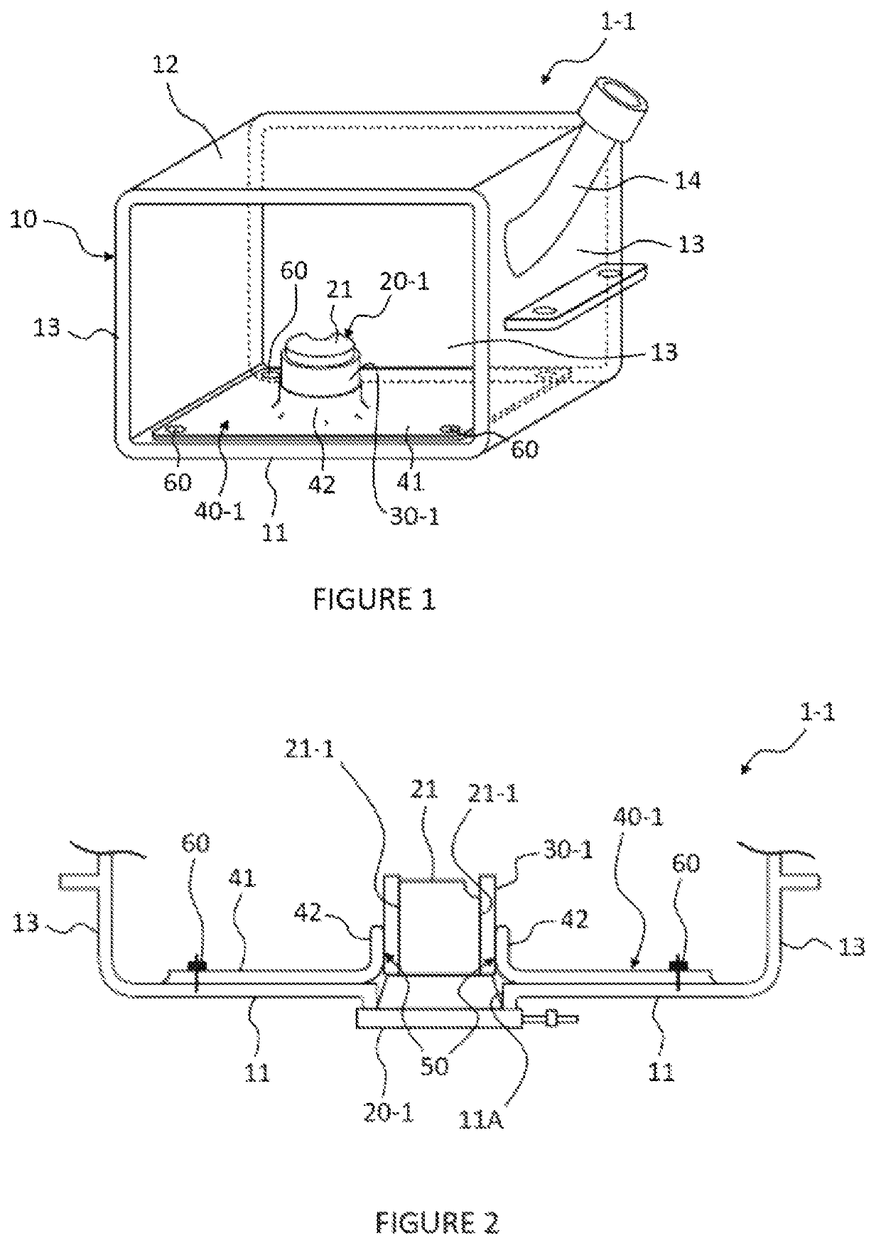
[0038]There is shown in FIG. 1 a first embodiment of the liquid storage device 1-1 according to the invention.

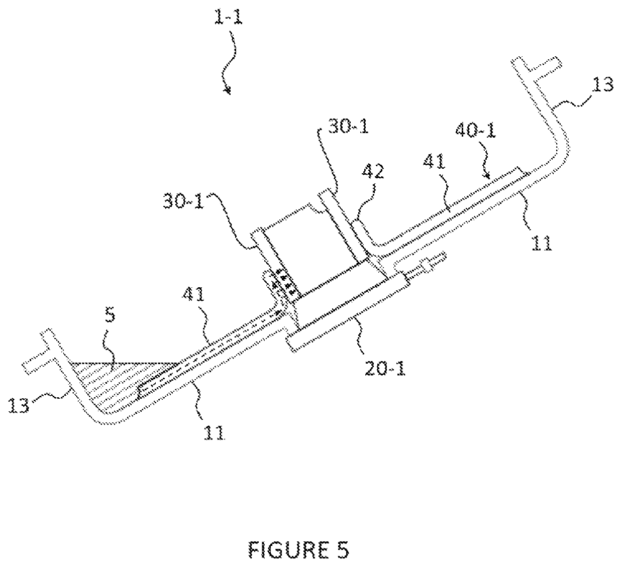
[0039]The device 1-1 according to the invention is intended to be mounted in a motor vehicle (not shown) in order to store a liquid 5 (visible in FIG. 5).

[0040]To this end, the device 1-1 comprises a reservoir 10, a pump 20-1, a filter 30-1 and a liquid 5 conveying member in the form of a mat 40-1.

[0041]In this example, the reservoir 10 is substantially of parallelepipedal shape. However, as a variant, the reservoir 10 could have any other shape, in particular a shape suitable for its integration into the vehicle. The reservoir 10 comprises in particular a lower wall, called “bottom” wall 11, an upper wall 12, side walls 13 and an introduction duct 14 for the liquid 5, mounted in this example on one of the side walls 13 and allowing the reservoir 10 to be filled with the liquid 5.

[0042]The reservoir 10 may contain a urea solution in order to control the emissions of harmful ...


PUM


Abstract

Disclosed is a device for storing a liquid for a motor vehicle, the device including a reservoir, including a bottom wall, a pump, mounted at an orifice formed at the bottom wall and including at least one portion extending through the orifice and including at least one suction nozzle, a filter mounted on the at least one portion of the pump at the at least one suction nozzle, and a mat arranged inside the reservoir at least partly on the bottom wall, the mat being able to move the liquid by capillarity and including a so-called “contact” portion being in contact with the filter at a contact surface in order to convey the liquid by capillarity to the filter.

Description

[0001]This application is the U.S. national phase of International Application No. PCT / EP2020 / 056956 filed Mar. 13, 2020 which designated the U.S. and claims priority to FR Patent Application No. 1902606 filed Mar. 14, 2019, the entire contents of each of which are hereby incorporated by reference.BACKGROUND OF THE INVENTIONField of the Invention[0002]The invention relates to the delivery of a liquid stored in a reservoir to a pump and more particularly to a device for storing a liquid for a motor vehicle comprising a reservoir and a pump mounted on a wall of said reservoir. The invention applies in particular to the device for storing water or urea solutions in motor vehicles.Description of the Related Art[0003]Nowadays, certain motor vehicles with an engine include in a known manner a storage device comprising a so-called “urea” reservoir which makes it possible to inject a urea solution into the gases discharged by the engine in order to reduce their harmfulness in the atmosphere...

Claims


Application Information

Patent Timeline
Patent Type & Authority Patents(United States)
IPC IPC(8): F01N1/00F01N3/20
CPCF01N3/2066F01N2610/02F01N2610/1406F01N2610/1426F01N2610/1433Y02A50/20Y02T10/12
Inventor MAGUIN, GEORGES
Owner VITESCO TECH GERMANY GMBH
Why Eureka
Try Eureka