Isochronous pivot for timepiece resonators

Active Publication Date: 2019-02-28
THE SWATCH GRP RES & DEVELONMENT LTD
View PDF0 Cites 2 Cited by
  • Summary
  • Abstract
  • Description
  • Claims
  • Application Information

AI Technical Summary

Benefits of technology

The invention is about a new kind of resonator that is easy to make and can withstand shocks without losing its quality. It uses a flexure pivot bearing, which ensures that it is always in the right time and can maintain a high-level performance.

Problems solved by technology

However, flexure pivot bearings are known to have a non-linear return force, and undesired movement of the instantaneous axis of rotation.
Such a pivot comprising two strips which cross in projection cannot, however, be etched in two dimensions in a single etch, which complicates manufacture.

Method used


Image

  • Isochronous pivot for timepiece resonators
  • Isochronous pivot for timepiece resonators
  • Isochronous pivot for timepiece resonators

Examples


Embodiment Construction

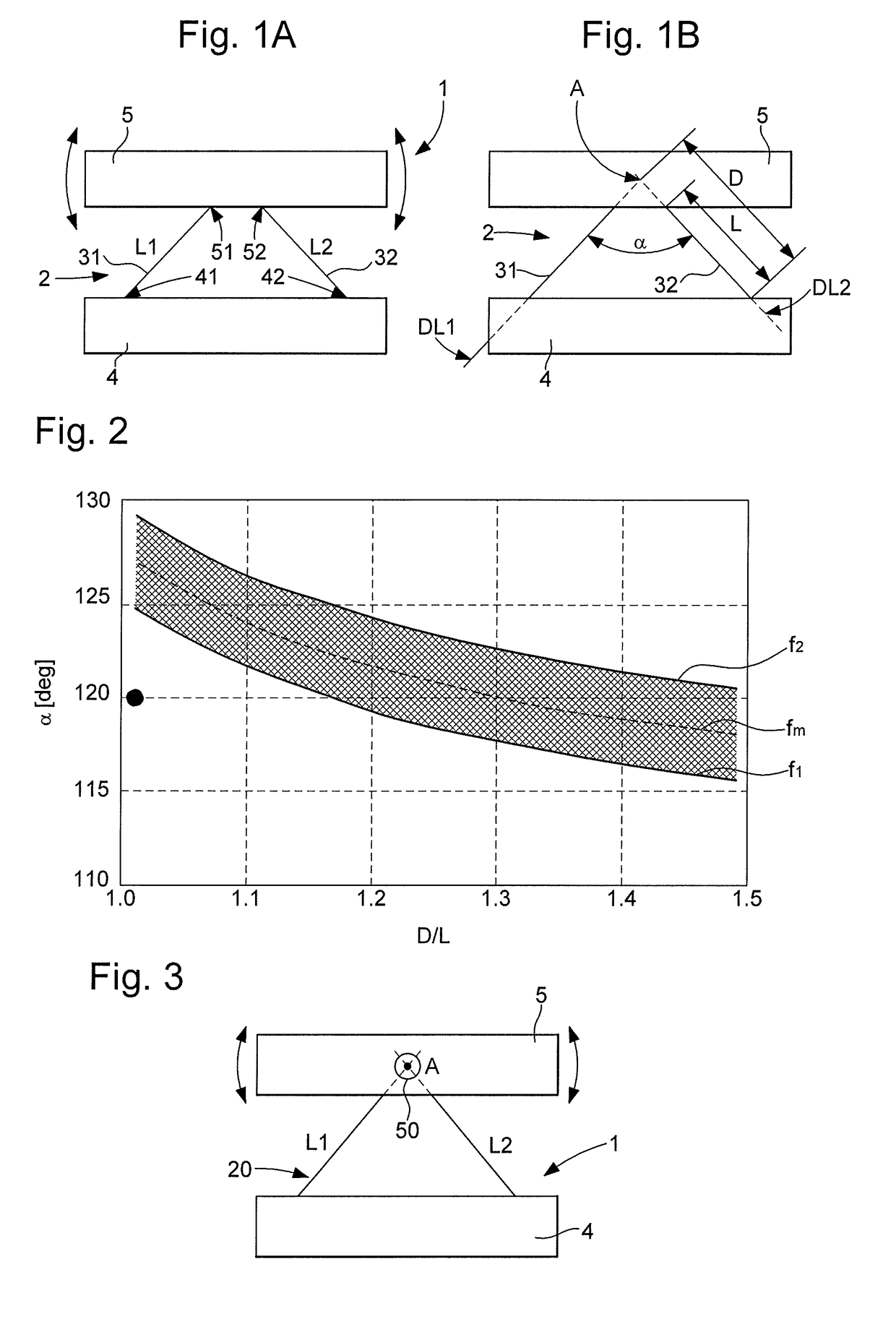
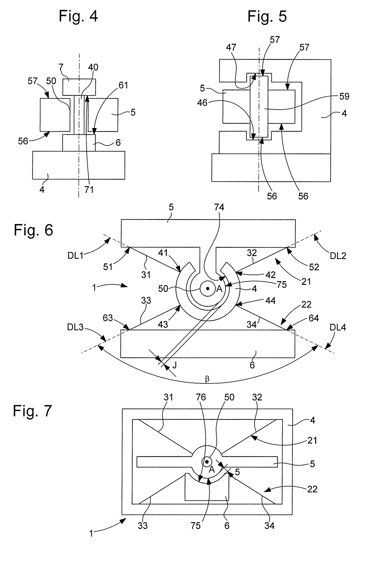
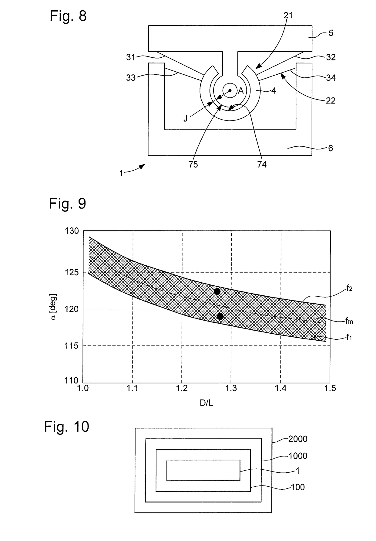
[0033]The invention concerns an isochronous pivot 1 for a timepiece resonator 100, with a flexure bearing, comprising at least one pair, generically denoted 2, or more particularly a first pair 21 or a second pair 22, according to the variants illustrated by the Figures. This pair 2 includes two flexible strips 3: 31, 32, each joining a first attachment point 41, 42 of a first element 4 to a second attachment point 51, 52 of a second element 5. These first attachment points 41, 42 define, with the respective second attachment points 51, 52, two main strip directions DL1 and DL2. The first element 4 and second element 5 are each stiffer than each of flexible strips 3, and each is able to form a movable inertial element inside a resonator 100.

[0034]The two strip directions DL1, DL2 define a theoretical pivot axis A, at their crossing point when the two flexible strips 31, 32 are coplanar, or at the crossing point of their projections onto a reference plane parallel to the two flexible...


PUM


Abstract

An isochronous pivot for a resonator including two flexible strips joining attachment points of a first and a second element, defining two strip directions, and a pivot axis, at the intersection of their projections or at their intersection, each strip having a free length between its attachment points, and an axial distance between the pivot axis and the attachment point thereof farthest from the axis, the attachment point ratio X=D / L being greater than one for each strip, the strip directions defining with the axis a first apex angle whose value in degrees includes between f1(X)=108+67 / (10X−6), and f2(X)=113+67 / (10X−6).

Description

[0001]This application claims priority from European Patent Application No. 17188264.0 filed on Aug. 29, 2017, the entire disclosure of which is hereby incorporated herein by reference.FIELD OF THE INVENTION[0002]The invention concerns an isochronous pivot for timepiece resonators, with a flexure bearing, comprising at least one pair including two flexible strips each joining a first point of attachment of a first element to a second point of attachment of a second element, said first attachment points defining, with said respective second attachment points, two main strip directions, said first element and said second element each being stiffer than each of said flexible strips, and each able to form a movable inertial element inside a said resonator, and said two main strip directions defining a theoretical pivot axis at their intersection when said two flexible strips are coplanar, or at the intersection of their projections onto a reference plane parallel to said two flexible st...

Claims


Application Information

Patent Timeline
IPC IPC(8): G04B31/00
CPCG04B31/00G04B17/045G04B17/32G04B17/20G04B17/28B81B3/0045G04B31/02
Inventor DI DOMENICO, GIANNILECHOT, DOMINIQUEFAVRE, JEROMEHINAUX, BAPTISTEBORN, JEAN-JACQUESHELFER, JEAN-LUCWINKLER, PASCAL
Owner THE SWATCH GRP RES & DEVELONMENT LTD
Why Eureka
Try Eureka