A trap or dispensing device

a technology of a dispensing device and a trap, which is applied in the direction of animal traps, projectiles, animal hunting, etc., can solve the problems of time-consuming and therefore costly processes

Inactive Publication Date: 2019-03-14
REDMAYNE JOHN MICHAEL
View PDF9 Cites 5 Cited by
  • Summary
  • Abstract
  • Description
  • Claims
  • Application Information

AI Technical Summary

Problems solved by technology

However, many traps and dispensing devices typically require a regular program of maintenance by a worker.
This can be a time consuming and therefore costly process.

Method used


Image

  • A trap or dispensing device
  • A trap or dispensing device
  • A trap or dispensing device

Examples


first embodiment

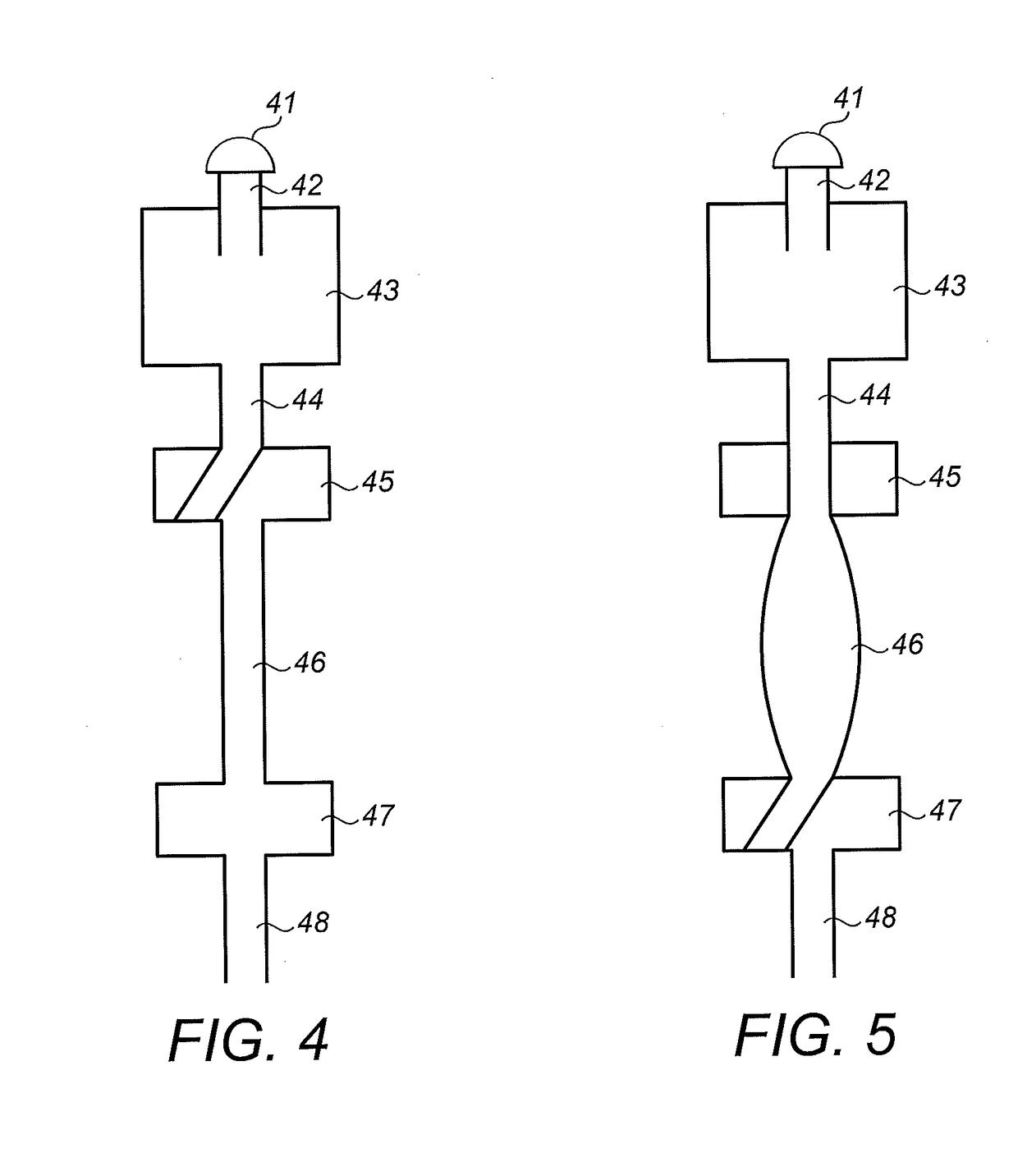
[0118]In a first embodiment, the lure metering system comprises a lower valve 47 that is normally open and an upper valve 45 that is normally closed. The lure metering system is configured to operate in response to a pulse of compressed gas as follows:[0119]a) Lower valve 47 is closed,[0120]b) Upper valve 45 is opened,[0121]c) Pressurised gas is introduced to the lure storage vessel 43,[0122]d) In this state (as illustrated in FIG. 5), lure is forced under pressure into the second, expandable lure flow path 46, which then expands to accommodate the lure,[0123]e) Upper valve 45 is closed,[0124]f) Lower valve 47 is opened, and[0125]g) In this state, lure is dispensed through the third lure flow path 48, causing the expandable lure flow path 46 to contract or at least substantially return to its non expanded state (i.e. from the state shown in FIG. 5 to the state shown in FIG. 4).

second embodiment

[0126]In a second embodiment, the lure metering system comprises a lower valve 47 that is normally closed and an upper valve 45 that is normally open. The lure metering system is configured to operate in response to a pulse of compressed gas as follows:[0127]a) Pressurised gas is introduced to the lure storage vessel 43,[0128]b) In this state (as illustrated in FIG. 5), lure is forced under pressure into the second, expandable lure flow path 46, which expands to accommodate the lure,[0129]c) Upper valve 45 is closed,[0130]d) Lower valve 47 is opened,[0131]e) In this state, lure is dispensed through the third lure flow path 48, causing the expandable lure flow path 46 to contract or to at least substantially return to its non expanded state (i.e. from the state shown in FIG. 5 to the state shown in FIG. 4),[0132]f) Lower valve 47 is closed, and[0133]g) Upper valve 45 is opened.

[0134]In these embodiments, the order of operations can be controlled by an electronic control system and / or...


PUM


Abstract

A trap comprising an apparatus to trap a target creature and a test activation system configured to initiate a test activation of the trap, wherein the test activation system comprises an electric power supply and an electronic control system powered by the electric power supply, wherein the electronic control system is configured to activate the trap to test the operation of the trap, and wherein the electronic control system is configured to activate the trap automatically according to a timer, programmed instructions or upon receipt of instructions from a user interface.

Description

FIELD OF THE INVENTION[0001]The present invention relates to a trap or dispensing device.BACKGROUND TO THE INVENTION[0002]Management of ecosystems, farming systems, pest control and so forth can require a number of tasks to be performed to control target creatures, such as pests. These tasks may include traps to kill the target creatures, dispensing devices to dispense poison or medication, and dispensing devices to dispense lure to attract target creatures for monitoring or observation.[0003]However, many traps and dispensing devices typically require a regular program of maintenance by a worker. For example, in the case of a kill trap, the trap needs to be checked regularly to remove any dead creatures, to reset the trap and replace the lure.[0004]Similarly, known dispensing devices frequently need to be monitored to remove old lure and replace that with fresh lure. This can be a time consuming and therefore costly process. Furthermore, there is a need to improve the operational a...

Claims


Application Information

Patent Timeline
Patent Type & Authority Applications(United States)
IPC IPC(8): A01M23/24A01M27/00A01M31/00
CPCA01M23/245A01M27/00A01M31/008A01M31/002A01M23/24
Inventor REDMAYNE, JOHN MICHAEL
Owner REDMAYNE JOHN MICHAEL
Why Eureka
Try Eureka