Method and apparatus for enhancing directional accuracy and control using bottomhole assembly bending measurements

a technology of bending measurement and directional accuracy, which is applied in the direction of directional drilling, borehole/well accessories, surveying, etc., can solve the problems of exacerbated problems, deviations from the desired wellbore path, and difficulty in further drilling and/or installation of production casings and other downhole equipmen

Inactive Publication Date: 2005-07-14
BAKER HUGHES INC
View PDF19 Cites 138 Cited by
  • Summary
  • Abstract
  • Description
  • Claims
  • Application Information

AI Technical Summary

Problems solved by technology

These bending moments cause deviations from the desired wellbore path that require corrections.
Commonly, high dogleg severity can cause difficulty in furthe

Method used


Image

  • Method and apparatus for enhancing directional accuracy and control using bottomhole assembly bending measurements
  • Method and apparatus for enhancing directional accuracy and control using bottomhole assembly bending measurements
  • Method and apparatus for enhancing directional accuracy and control using bottomhole assembly bending measurements

Examples


Embodiment Construction

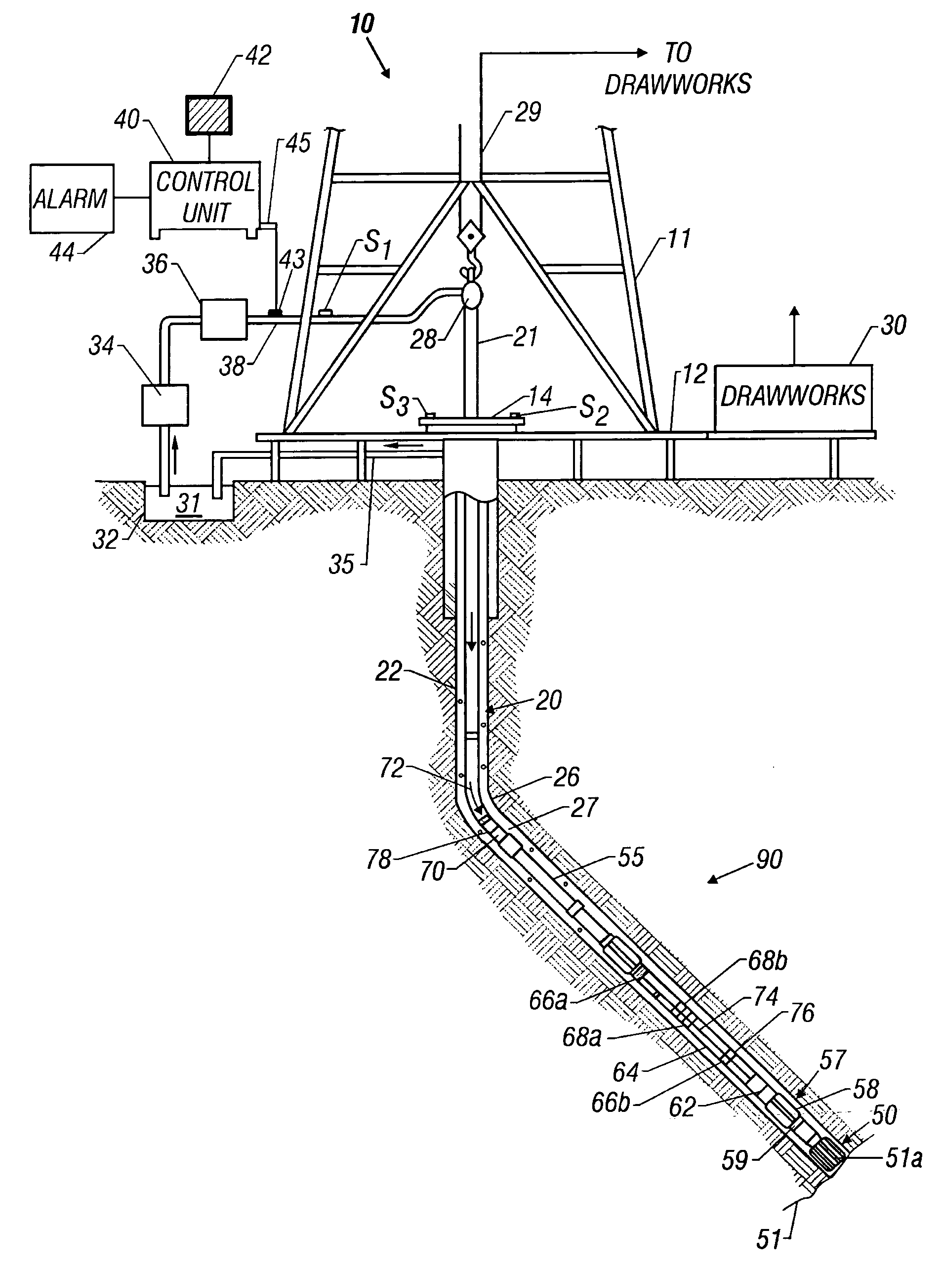
[0024]FIG. 1 shows a schematic diagram of a drilling system 10 having a drilling assembly 90 shown conveyed in a borehole 26 for drilling the wellbore. The drilling system 10 includes a conventional derrick 11 erected on a floor 12 which supports a rotary table 14 that is rotated by a prime mover such as an electric motor (not shown) at a desired rotational speed. The drill string 20 includes a drill pipe 22 extending downward from the rotary table 14 into the borehole 26. A drill bit 50, attached to the drill string end, disintegrates the geological formations when it is rotated to drill the borehole 26. The drill string 20 is coupled to a drawworks 30 via a kelly joint 21, swivel 28 and line 29 through a pulley 23. During the drilling operation the drawworks 30 is operated to control the weight on bit, which is an important parameter that affects the rate of penetration. The operation of the drawworks 30 is well known in the art and is thus not described in detail herein.

[0025] D...


PUM


Abstract

A system for drilling a well comprises a tubular member having a bottomhole assembly at a bottom end thereof disposed in a wellbore. A first sensor is disposed in the bottomhole assembly at a predetermined axial location for detecting bending in a first axis and generating a first bending signal in response thereto, where the first axis is substantially orthogonal to a longitudinal axis of the bottomhole assembly. A second sensor is disposed in the bottomhole assembly at the predetermined axial location for detecting bending in a second axis and generating a second bending signal in response thereto, where the second axis is substantially orthogonal to the longitudinal axis. A processor receives the first bending signal and the second bending signal and relates the first bending signal and the second bending signal to a borehole curvature according to programmed instructions.

Description

CROSS REFERENCE TO RELATED APPLICATIONS [0001] This application claims the benefit of U.S. Provisional Application No. 60 / 531,392, filed Dec. 19, 2003.FIELD OF THE INVENTION [0002] This invention generally relates to logging while drilling. More specifically this invention relates to a method, system, and apparatus for predicting curvature of a wellbore form bending moment measurements and for adjusting downhole steerable systems based on such measurements. BACKGROUND OF THE INVENTION [0003] To obtain hydrocarbons such as oil and gas, boreholes are drilled by rotating a drill bit attached at a drill string end. A large proportion of the current drilling activity involves directional drilling, i.e., drilling deviated and horizontal boreholes, to increase the hydrocarbon production and / or to withdraw additional hydrocarbons from the earth's formations. Modem directional drilling systems generally employ a drill string having a bottomhole assembly (BHA) and a drill bit at end thereof t...

Claims


Application Information

Patent Timeline
IPC IPC(8): E21B7/06E21B47/00E21B47/022E21B47/024
CPCE21B7/06E21B47/022E21B47/0006E21B47/007E21B47/024
Inventor JOGI, PUSHKARNEUBERT, MICHAELMACPHERSON, JOHN D.HOOD, JAMESDAHL, THOMASKRUEGER, VOLKERBROOKS, ANDREW G.HEISIG, GERALD
Owner BAKER HUGHES INC
Why Eureka
Try Eureka