Work machine and control method for work machine

a technology of work machine and control method, which is applied in mechanical machines/dredgers, servomotors, construction, etc., can solve the problems of difficult to achieve accurate land grading and difficult to perform intervention control of target shape of object of execution

Active Publication Date: 2019-03-14
KOMATSU LTD
View PDF1 Cites 4 Cited by
  • Summary
  • Abstract
  • Description
  • Claims
  • Application Information

AI Technical Summary

Benefits of technology

[0012]The work machine and the control method for the wor

Problems solved by technology

In some situations, this intervention control for the target shape of the object of execution is difficult to perform depending on the operation speed of the work implement.
More specifically, when a res

Method used


Image

  • Work machine and control method for work machine
  • Work machine and control method for work machine
  • Work machine and control method for work machine

Examples


Embodiment Construction

[0024]An embodiment of the present invention is hereinafter described with reference to the drawings. In the following description, identical parts are given identical reference numbers. These identical parts have identical names and functions, wherefore details of these parts are not repeatedly described herein. Note that “upper”, “lower”, “fore”, “after”, “left”, and “right” in the following description are terms defined as viewed from a reference corresponding to an operator sitting on an operator's seat.

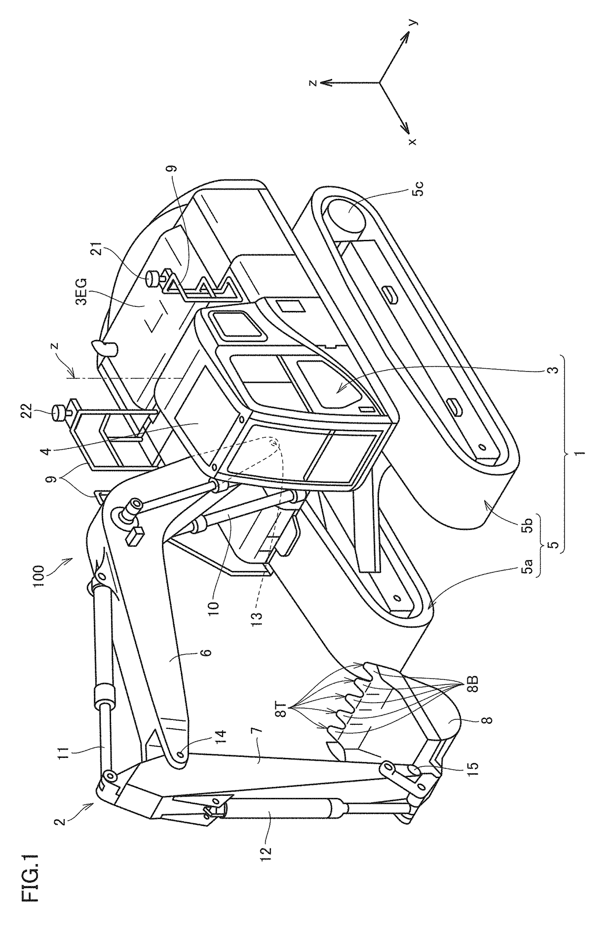
[0025]FIG. 1 is a perspective view of a work machine according to the embodiment.

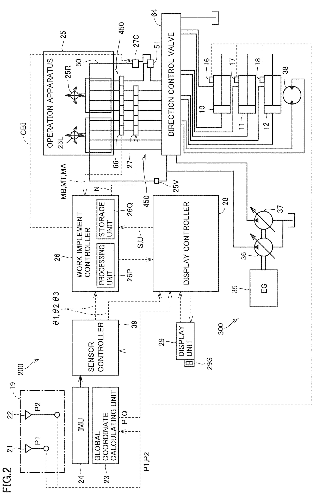
[0026]FIG. 2 is a block diagram illustrating configurations of a control system 200 and a hydraulic system 300 included in a hydraulic excavator 100 according to the embodiment.

[0027]Referring to FIG. 1, hydraulic excavator 100 provided as a work machine includes a vehicular body 1 and a work implement 2.

[0028]Vehicular body 1 includes an upper revolving unit 3 provided as a revolving unit, and a tra...


PUM


Abstract

A work machine according to an aspect includes: a dipper stick; a boom; a cylinder for driving the boom; an operation apparatus for operating the dipper stick; and a controller for performing intervention control by using the boom in accordance with an operation command issued from the operation apparatus to achieve land grading. The controller determines whether or not the operation command from the operation apparatus indicates an amount greater than or equal to a predetermined amount, and corrects a speed of the cylinder when the operation command from the operation apparatus indicates an amount greater than or equal to the predetermined amount.

Description

TECHNICAL FIELD[0001]The present invention relates to a work machine including a work implement, and a control method for a work machine.BACKGROUND ART[0002]For a work machine that includes a front device provided with a bucket, there has been proposed such control that shifts the bucket along a boundary surface defining a target shape of an object of execution (for example, see PTD 1). This control is referred to as intervention control.[0003]In some situations, this intervention control for the target shape of the object of execution is difficult to perform depending on the operation speed of the work implement.[0004]More specifically, when a response delay of a boom is produced by the intervention control during a high-speed movement of a dipper stick, for example, for performing land grading, accurate land grading may be difficult to achieve.CITATION LISTPatent Document[0005]PTD 1: WO 2016 / 035898SUMMARY OF INVENTIONTechnical Problem[0006]The present disclosure has been developed...

Claims


Application Information

Patent Timeline
IPC IPC(8): E02F3/43E02F9/20E02F9/22E02F3/32E02F9/26
CPCE02F3/435E02F9/2004E02F9/2203E02F3/32E02F9/2292E02F9/2296E02F9/2235E02F9/262E02F9/22E02F3/437F15B21/087F15B11/08F15B2211/6336E02F9/2037E02F9/2285
Inventor YAMADA, TAKEOOHKUMA, AYUMIMATSUYAMA, TORU
Owner KOMATSU LTD
Why Eureka
Try Eureka