Apparatus for handling a turbomachine part

a technology for turbomachines and parts, applied in mechanical apparatus, machines/engines, engine components, etc., can solve the problems of prior art methods and the necessity of having personnel inside the turbomachine package, and achieve the effects of reducing machine downtime, reducing the number of parts

Active Publication Date: 2019-03-14
NUOVO PIGNONE TECH SRL
View PDF2 Cites 121 Cited by
  • Summary
  • Abstract
  • Description
  • Claims
  • Application Information

AI Technical Summary

Benefits of technology

[0010]This technical result translates into a reduction of machine downtime and, therefore, in an economic saving. A further reason of economic saving is obtained both thanks to the shortest time during which the machine remains off and thanks to the fact that the disassembly and reassembly operations are easier, more rapid and require the presence of a lower number of technicians.
[0011]Furthermore, the apparatus according to embodiments of the present invention allows dramatically increase the level of safety of the disassembly and reassembly operations of the turbomachine parts, in particular of the stator cone of a gas turbine, since it allows to avoid the presence of people inside of the package of the machine during the operations, allowing to handle the turbine portion in a completely automatic way, the apparatus being, in an embodiment, remotely operated by the personnel which is outside the area of movement of the suspended load, in a more safe condition.
[0012]Additionally, the apparatus according to embodiments of the present invention, due to the fact that the turbine part, e.g. the stator cone, is secured to an apparatus part and then lifted by the lifting apparatus, allows the movement of the stator cone in a safer way which avoids the possibility of dangerous oscillations of the appended load.

Problems solved by technology

A first drawback of the disassembly method according to the prior art is that, in order to access the stator cone from the above, it is necessary to completely disassemble the enclosure in which the turbomachine is housed and also part of the turbine module into which the stator cone is inserted.
A further drawback afflicting the prior art method is the necessity to have personnel inside the turbomachine package during the assembling and disassembling operations.

Method used


Image

  • Apparatus for handling a turbomachine part
  • Apparatus for handling a turbomachine part
  • Apparatus for handling a turbomachine part

Examples


Embodiment Construction

[0026]The following description of exemplary embodiments refers to the accompanying drawings. The following detailed description does not limit embodiments of the invention. Instead, the scope of embodiments of the invention is defined by the appended claims.

[0027]Reference throughout the specification to “one embodiment” or “an embodiment” means that a particular feature, structure, or characteristic described in connection with an embodiment is included in at least one embodiment of the subject matter disclosed. Thus, the appearance of the phrases “in one embodiment” or “in an embodiment” in various places throughout the specification is not necessarily referring to the same embodiment. Further, the particular features, structures or characteristics may be combined in any suitable manner in one or more embodiments.

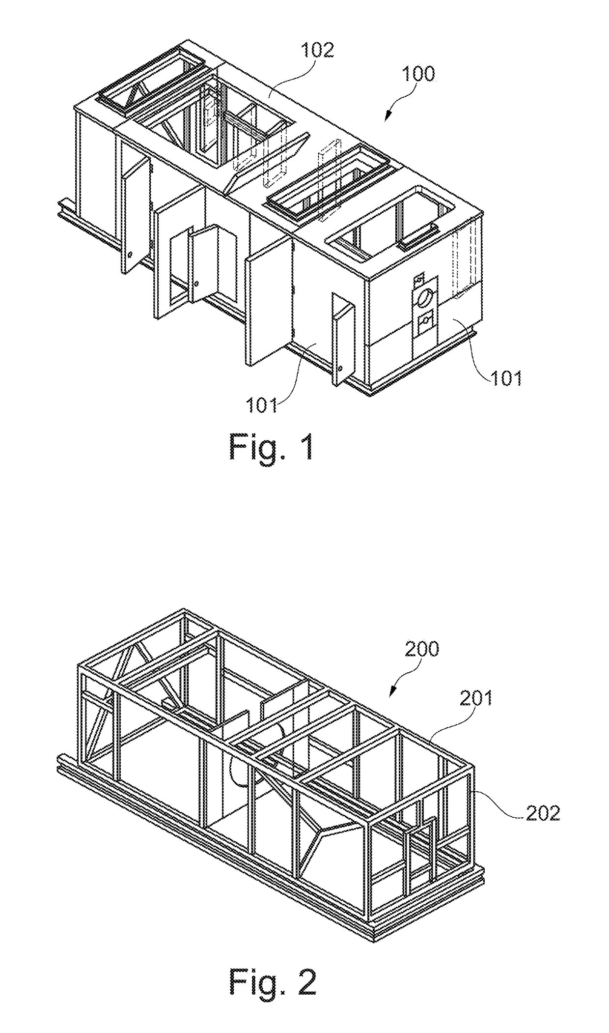
[0028]With reference to FIGS. 1 and 2, a turbomachine, and more particularly a gas turbine 400, is usually housed in an enclosure 100 having lateral walls 101 and a ceil...


PUM


Abstract

An apparatus for handling a turbomachine part, particularly during disassembling and reassembling operations. More specifically, an apparatus for handling the stator cone of a gas turbine suitable to completely manipulate the stator cone during disassembling and reassembling operations. The apparatus allows to disassemble and reassemble the stator cone of a gas turbine without the need to dismount the turbomachine enclosure and without the necessity to have personnel inside the turbomachine package during the operations.

Description

BACKGROUND OF THE INVENTION[0001]Embodiments of the present invention relate to an apparatus for handling a turbomachine part, particularly during disassembling and reassembling operations.[0002]More specifically, embodiments of the present invention relate to an apparatus for handling the stator component of a gas turbine suitable to completely manipulate said stator component during disassembling and reassembling operations.[0003]The stator component, having a conical shape and therefore referred to also as stator cone, supports the turbine module and has a sealing function in order to prevent leakage of hot gases. Additionally the stator cone has a function of thermal insulation and separation between the turbine compartment and the exhaust duct.[0004]The gas turbine is usually housed in a housing structure or enclosure. Said enclosure comprises a support structure constituted by a plurality of beams and pillars, said support structure being closed by panels that form lateral wal...

Claims


Application Information

Patent Timeline
Patent Type & Authority Applications(United States)
IPC IPC(8): F01D25/28
CPCF01D25/285F05D2230/644F05D2230/70F05D2250/232F05D2260/30
Inventor BRAGLIA, GIACOMOALVINO, GIANPAOLOMOCHI, GIANNIRIGHESCHI, ANDREA
Owner NUOVO PIGNONE TECH SRL
Why Eureka
Try Eureka