Refrigerator
- Summary
- Abstract
- Description
- Claims
- Application Information
AI Technical Summary
Benefits of technology
Problems solved by technology
Method used
Image
Examples
embodiment 1
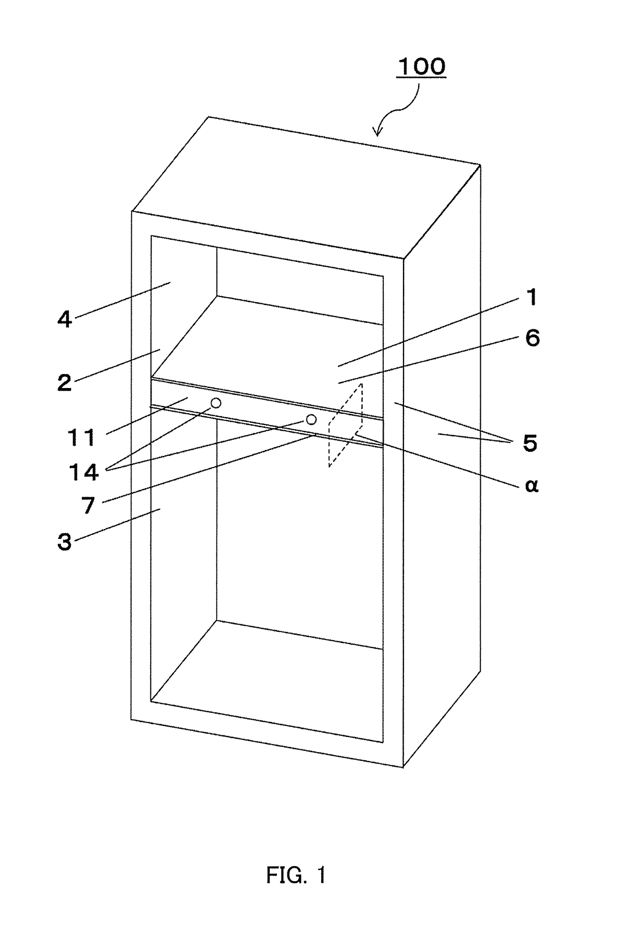
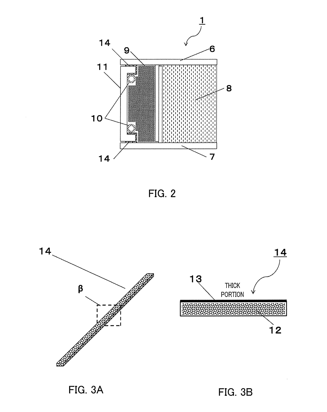
[0065]FIG. 1 is a view illustrating a heat insulating box of a refrigerator according to Embodiment 1 of the present invention, and FIG. 2 is a longitudinal cross-sectional view of portion α in FIG. 1.
[0066]100>
[0067]In FIG. 1, a refrigerator 100 includes outer box 5 made of metal such as a steel plate, inner box 4 made of resin such as an acrylonitrile-butadiene-styrene (ABS), and partition plate 1. Partition plate 1 is a partition that vertically partitions first storage room 2 and second storage room 3, and is disposed between rooms having different temperature zones such as a chiller serving as first storage room 2 and a freezer serving as second storage room 3.
[0068]1>
[0069]In FIG. 2, partition plate 1 includes upper plate 6 and lower plate 7 on upper and lower sides, and heat radiation pipe 10 of a refrigerating cycle is provided on a front surface portion (front surface of the refrigerator) of upper plate 6 and lower plate 7 in such a manner that heat radiation pipe 10 is in ...
embodiment 2
[0119]Embodiment 2 will be described with reference to FIG. 12. FIG. 12 is a longitudinal cross-sectional view of portion α in FIG. 1. In Embodiment 2, a configuration and a method of manufacturing refrigerator 100, a method of manufacturing partition plate 1, and a method of manufacturing soft composite heat insulating material 12 and laminated heat insulator 14 are the same as those in Embodiment 1. The present embodiment is different from Embodiment 1 in a method of mounting laminated heat insulator 14 on design plate 11 illustrated in FIG. 12. Items not to be described are the same as those in above-described Embodiment 1.
[0120]14 on Design Plate 11>
[0121]A method of mounting laminated heat insulator 14 on design plate 11 is illustrated in FIG. 13. Laminated heat insulator 14 includes surface A in which laminate film 13 is thick, and surface B in which laminate film 13 is thin. As illustrated in FIG. 13, laminated heat insulator 14 is attached to a substantially U-shaped side su...
embodiment 3
[0128]Laminated heat insulator 14 is mounted on design plate 11 in Embodiment 3, which will be described with reference to FIG. 15. Items not to be described are similar to those in above-described Embodiments.
[0129]14 on Design Plate 11>
[0130]A method of mounting laminated heat insulator 14 on design plate 11 is illustrated in FIG. 15. Laminated heat insulator 14 includes surface A in which laminate film 13 is thick, and surface B in which laminate film 13 is thin. As illustrated in FIG. 13, laminated heat insulator 14 is attached to a substantially U-shaped side surface of design plate 11 with thin surface B serving as a mounting surface. It is different from the configuration of Embodiment 1 in that a surface of laminated heat insulator 14 to be attached to design plate 11 is only two surfaces as illustrated in the drawing. Further, a position of the two surfaces to be attached is different from that in Embodiment 2.
[0131]1>
[0132]A method of manufacturing partition plate 1 will b...
PUM
 Abstract
Description
Claims
Application Information
 - R&D
- Intellectual Property
- Life Sciences
- Materials
- Tech Scout
- Unparalleled Data Quality
- Higher Quality Content
- 60% Fewer Hallucinations
Browse by: Latest US Patents, China's latest patents, Technical Efficacy Thesaurus, Application Domain, Technology Topic, Popular Technical Reports.
© 2025 PatSnap. All rights reserved.Legal|Privacy policy|Modern Slavery Act Transparency Statement|Sitemap|About US| Contact US: help@patsnap.com


