Method for transmitting and receiving uplink data channel, and apparatus thereof

a technology of uplink data and transmission method, applied in the field of mobile communication system, to achieve the effect of high reception quality and low delay tim

Inactive Publication Date: 2019-03-14
ELECTRONICS & TELECOMM RES INST
View PDF2 Cites 54 Cited by
  • Summary
  • Abstract
  • Description
  • Claims
  • Application Information

AI Technical Summary

Benefits of technology

[0027]According to the embodiments of the present disclosure, a low delay time and a high reception quality of a mobile communication system can be achieved.

Problems solved by technology

However, according to this scheme, since it takes a large delay time from when the terminal transmits the SR to when the terminal receives an uplink grant, a method of omitting the round trip latency between the terminal and the serving base station is required.

Method used

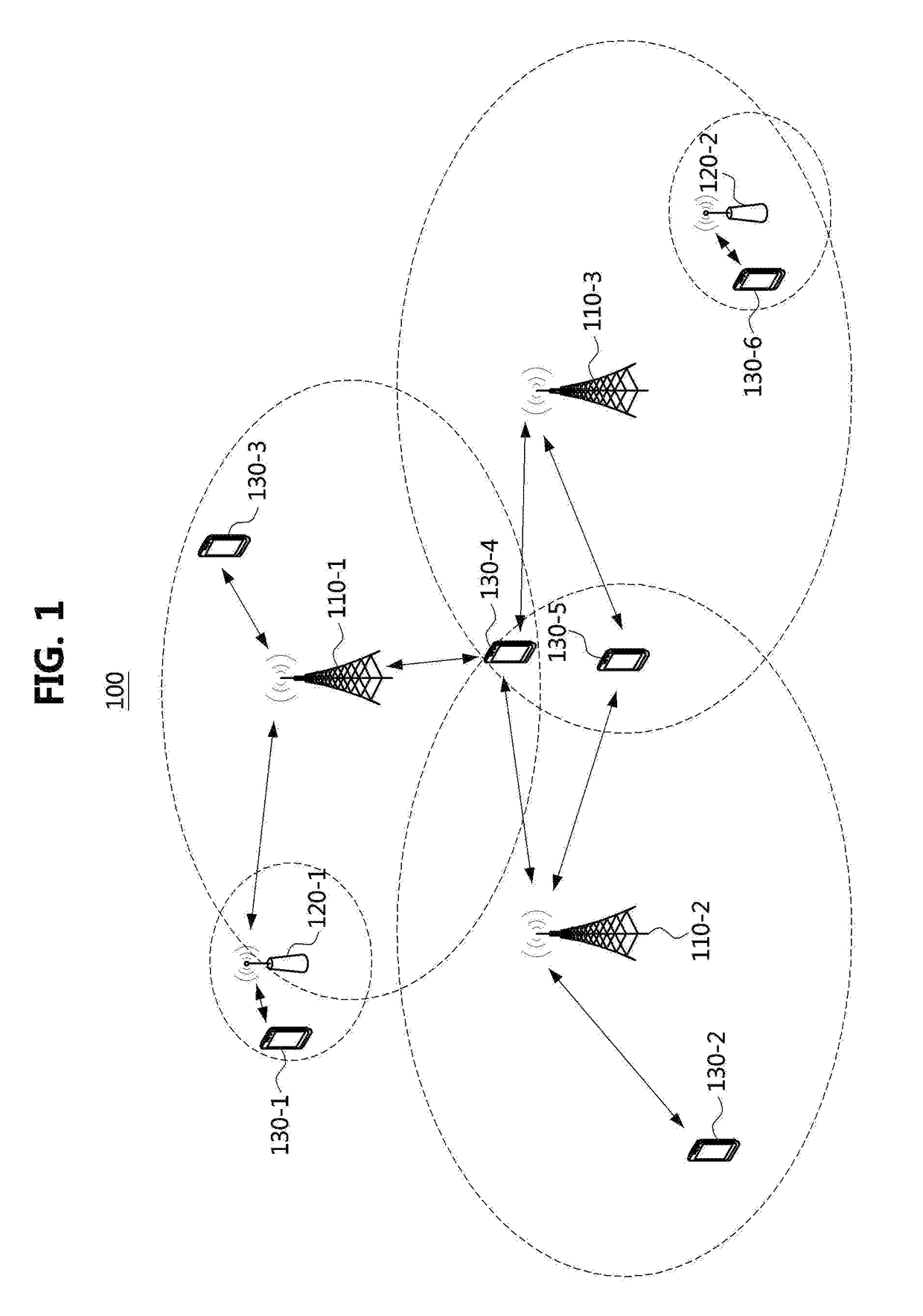
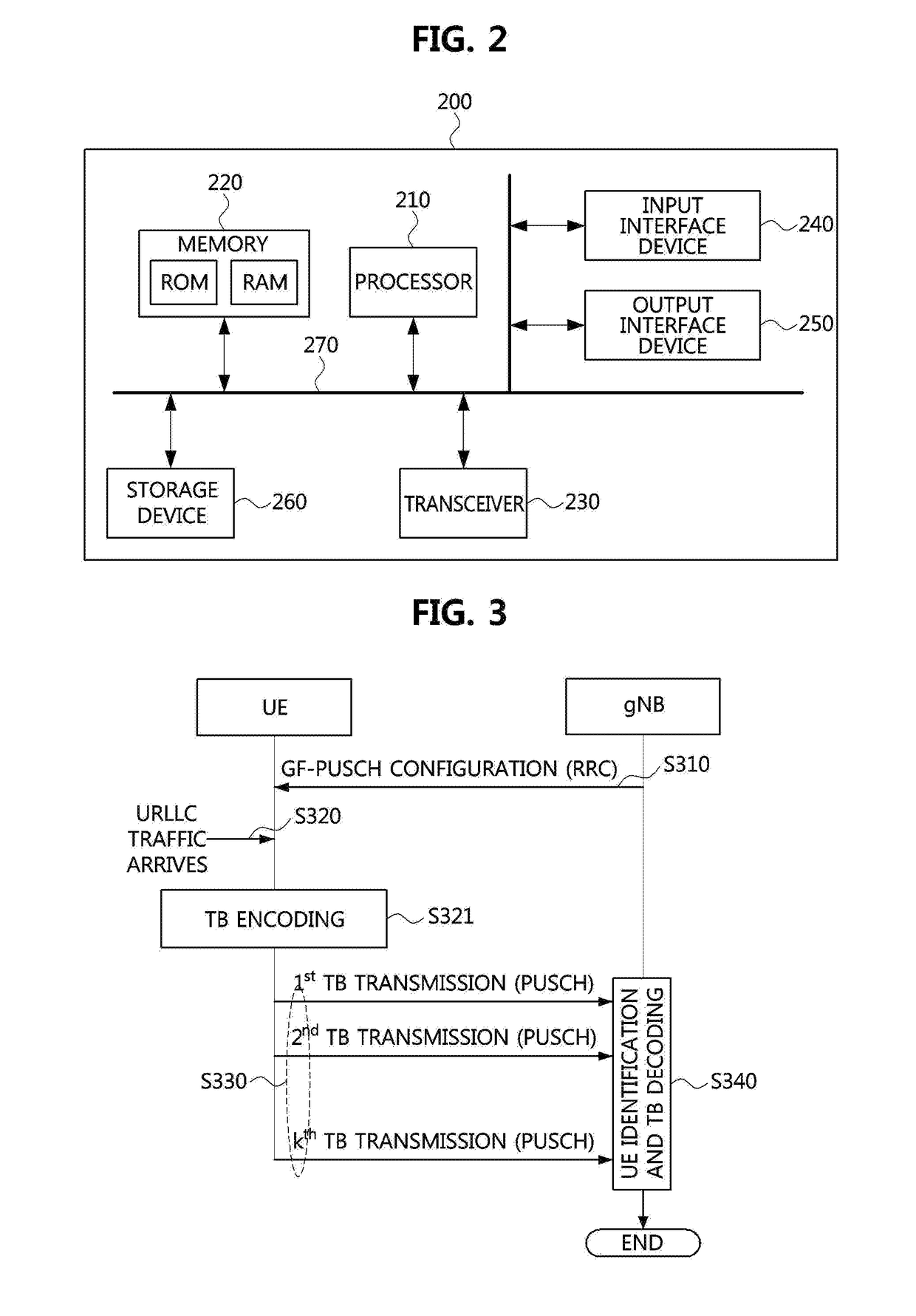
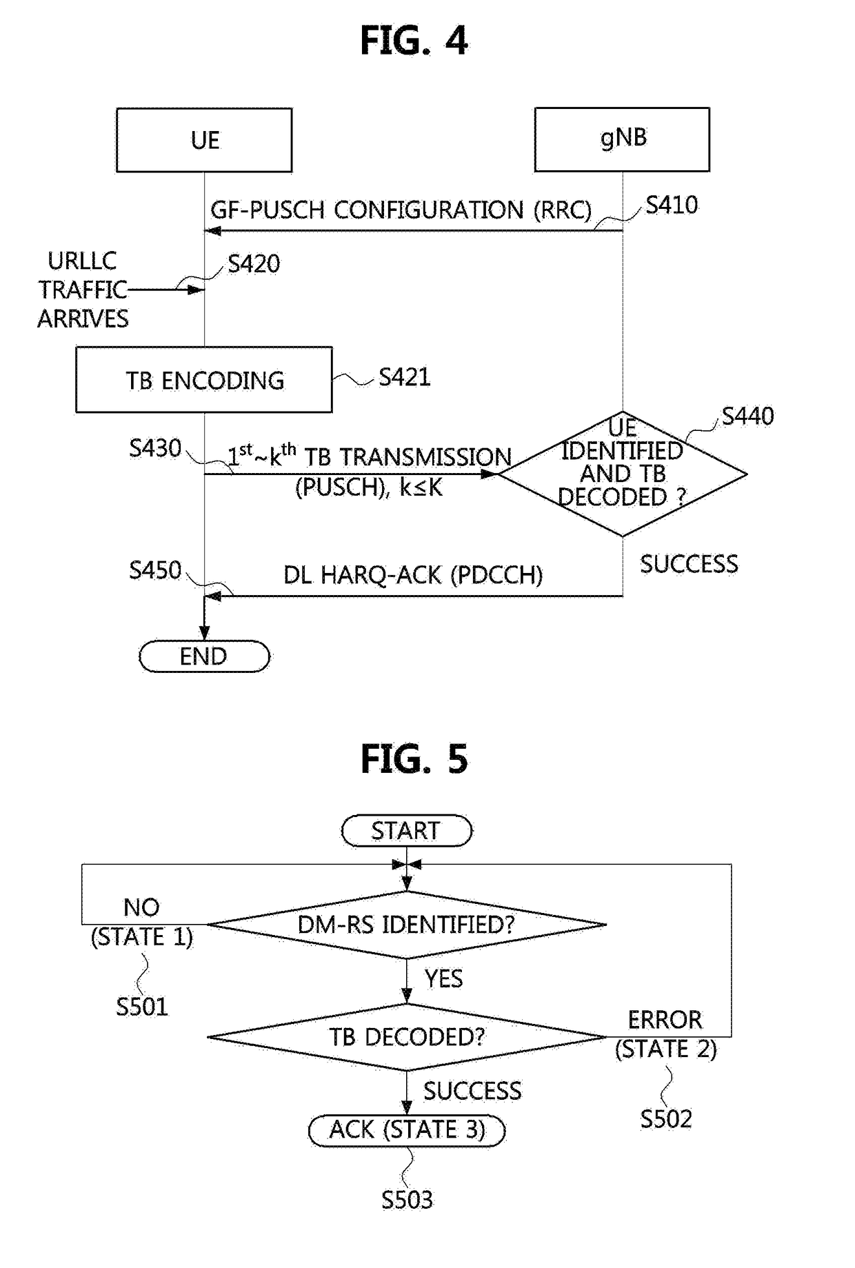

Image

  • Method for transmitting and receiving uplink data channel, and apparatus thereof
  • Method for transmitting and receiving uplink data channel, and apparatus thereof
  • Method for transmitting and receiving uplink data channel, and apparatus thereof

Examples


first example

① First Example

[0225]The serving base station may configure N (≥1) frequency resources available for the SR to the UE through the RRC signaling. Then, the serving base station may notify a CSIT to the UE through a PDSCH. The UE may know which frequency resource channel gain is higher according to the CSIT. When the UE needs to transmit the SR, the UE may select a frequency resource with the highest channel gain among the frequency resources, and transmit the SR in the selected frequency resource. The serving base station may know the frequency resource selected by the UE in advance, and thus may not perform a blind detection. In the case where a channel reciprocity is fully or partially established, the UE may estimate the CSIT using a DL RS even if the serving base station does not transmit the CSIT to the UE, so that the corresponding procedure may be omitted.

second example

② Second Example

[0226]The serving base station may configure N (≥1) frequency resources available for the SR to the UE through the RRC signaling. Then, the serving base station may inform the UE of an index indicating a frequency resource among the frequency resources. As a method for this, an index may be transmitted using a PDCCH, or an SR resource using a specific frequency resource may be activated or deactivated using a MAC control element (CE). When the UE needs to transmit the SR, the UE may transmit the SR in the SR resource corresponding to the index received from the serving base station or in the SR resource activated by the MAC CE.

[0227]When the index of the frequency resource used for transmitting the SR is changed, the serving base station may notify the updated index to the UE using the PDCCH or the MAC CE. For this, the serving base station may transmit a periodic PDCCH or a periodic MAC CE to the UE. Alternatively, in an environment where the mobility of the UE is s...

third example

③ Third Example

[0229]The serving base station may configure N (≥1) frequency resources available for the SR to the UE through the RRC signaling. The UE may receive a DL physical layer signal and a DL physical channel from the serving base station, and apply the channel reciprocity to estimate a UL channel response roughly. Based on this, the UE may select one frequency resource used by the SR. Unlike the above-described examples (the first example and the second example), there is an advantage that the signaling overhead is small because the serving base station does not explicitly indicate the frequency resource to the UE. If the serving base station also estimates the UL channel response through a sounding reference signal (SRS) or the like, and knows which frequency resource the UE selects, the serving base station may not perform a blind detection. However, if the serving base station does not trust antenna calibration of the UE, it may be preferable to perform the blind detecti...


PUM


Abstract

A method of transmitting a grant-free uplink data channel (physical uplink shared channel (PUSCH)) (GF-PUSCH), performed in a terminal, includes determining a resource (GF-PUSCH resource) for transmission of the GF-PUSCH and an identifier (DM-RS ID) of a demodulation reference signal (DM-RS) included in the GF-PUSCH; when an uplink traffic arrives, encoding the uplink traffic into a transport block (TB); generating the DM-RS based on the DM-RS ID, and transmitting the GF-PUSCH including the TB and the DM-RS to a base station through the GF-PUSCH resource; and receiving, from the base station, a group hybrid automatic repeat request acknowledgement (HARQ-ACK) information in which ACK or negative acknowledgement (ACK / NACK) information for the GF-PUSCH of the terminal and ACK / NACK information for at least one GF-PUSCH of at least one other terminal are multiplexed, through a downlink control information (DCI).

Description

CROSS-REFERENCE TO RELATED APPLICATIONS[0001]This application claims priority to Korean Patent Application Nos. 10-2017-0115433, filed Sep. 8, 2017, 10-2017-0126155, filed Sep. 28, 2017, 10-2017-0136089, filed Oct. 19, 2017, 10-2018-0034050, filed Mar. 23, 2018, 10-2018-0053229, filed May 9, 2018, 10-2018-0066997, filed Jun. 11, 2018, and 10-2018-0093037, filed Aug. 9, 2018, in the Korean Intellectual Property Office (KIPO), the entire contents of which are hereby incorporated by reference.BACKGROUND1. Technical Field[0002]The present disclosure relates to a mobile communication system, more specifically, to a method for transmitting and receiving a grant-free uplink (UL) data channel, a method for transmitting and receiving downlink control information for the grant-free uplink data channel, and an apparatus for the same.2. Description of Related Art[0003]In the Ultra-Reliable Low-Latency Communication (URLLC) supported by the 3rd Generation Partnership Project (3GPP) New Radio (NR...

Claims


Application Information

Patent Timeline
Patent Type & Authority Applications(United States)
IPC IPC(8): H04W72/12H04L5/00
CPCH04W72/1284H04L5/0055H04W74/08H04L1/0073H04L1/08H04L1/1671H04L1/1854H04L1/1887H04L5/0023H04L5/001H04L5/0035H04L5/0048H04L5/0091H04L5/14H04L27/2602H04L27/26025H04B7/0404H04B7/0408H04B7/0456H04L1/1864H04L1/1614H04L1/1621H04L1/1812H04L5/005H04W72/23H04L27/26H04W72/21
Inventor KIM, CHEUL SOONMOON, SUNG HYUNYEH, CHOONG ILLEE, JUNG HOON
Owner ELECTRONICS & TELECOMM RES INST
Why Eureka
Try Eureka