
Motorized window shades for RVs

a motorized and rv technology, applied in the direction of sunshades, door/window protective devices, transportation and packaging, etc., can solve the problems of manual operable shades not having the same top-to-bottom alignment problems, motorized shades are more expensive than manual operable shades, etc., to increase the aesthetic appeal of rvs

Active Publication Date: 2019-03-21
JAYCO INC
View PDF19 Cites 2 Cited by
  • Summary
  • Abstract
  • Description
  • Claims
  • Application Information

AI Technical Summary

Benefits of technology

The present invention is a motorized shade assembly for RV windows that can cover inclined or curved windows without sagging or misalignment. It increases the aesthetic appeal of the RV. The shade assembly includes a discontinuous web that extends between two rollers, one of which is motorized and the other is tensioned or biased towards rotation away from the other roller. The shade assembly can be easily positioned between an inclined or curved window and an interior shroud for the window and can be hardwired or wirelessly controlled by the user.

Problems solved by technology

However, motorized shades tend to be more expensive than manually operable shades, and typically require more bulky mechanisms.
For example, manually operable shades may not have the same top-to-bottom alignment problems in use, because only a single roller can suffice, with bottom “fall” being adjustable by the using during actuation.
Motorized shades using top and bottom rollers, however, usually need a means of ensuring proper alignment between the rollers, especially over an extended period of time.
Alignment solutions which have been available for those motorized shades often employ heavy, expensive, and / or oversized frames or structural features.
Further, motorized (as well as manual) shades used in static structures have run into operational difficulties where the window to be covered is inclined with respect to the vertical plane and / or has a curvature into the horizontal plane.
Especially in connection with wide windows, using shades with inclined or curved windows runs the risk of shade sag, or spacial separation from the desired window distance to be maintained by the shade from the window.
Prior shades have reduced sag by forming the shade web from rigid material, but that often increases shade cost and weight.
However, in addition to increasing cost and overall weight of the shade assembly, such devices increase the actuation torque needed by operating motors (often requiring a larger and / or more expensive motor) or the force needed to be exerted by the manual user.
Further, using shades in vehicles can create additional difficulties.
Spacial constraints in vehicles are generally more severe than in static structures.
Thus, some of the frame and support structures that may be acceptable for motorized shades in static structures is not well suited for use in vehicles.
Similarly, costs that may be acceptable for motorized shades in residences and office buildings are not acceptable for production of vehicles, where the user market for vehicles can be much more price sensitive.
Prior attempts to use motorized shades for such cab-over windows have encountered shade sag, snagging of the shade web with the side and / or bottom edges of the shroud opening, and misalignment of the shade (even when using cord draw strings, since the “winding diameter” can be non-uniform from time to time).
These prior attempts have also involved motorized shades whose cost, installation time, and maintenance have been undesirably high.

Method used


Image

  • Motorized window shades for RVs
  • Motorized window shades for RVs
  • Motorized window shades for RVs

Examples


Embodiment Construction

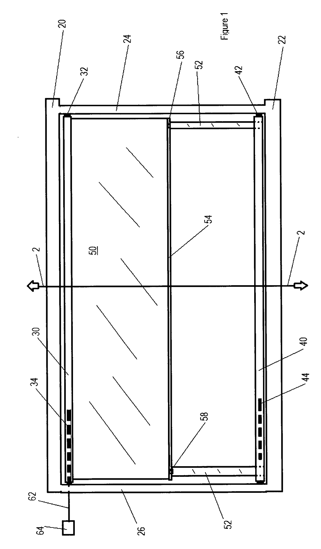
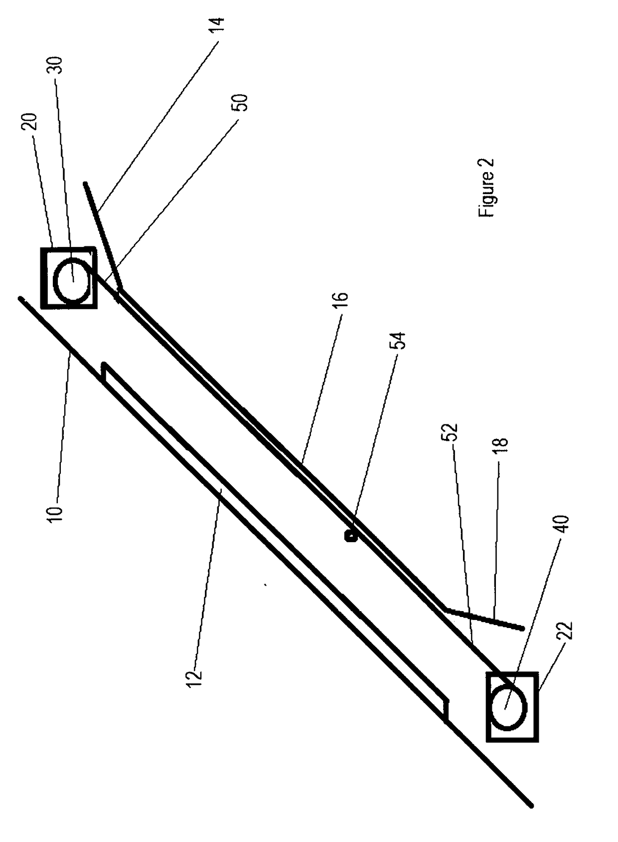
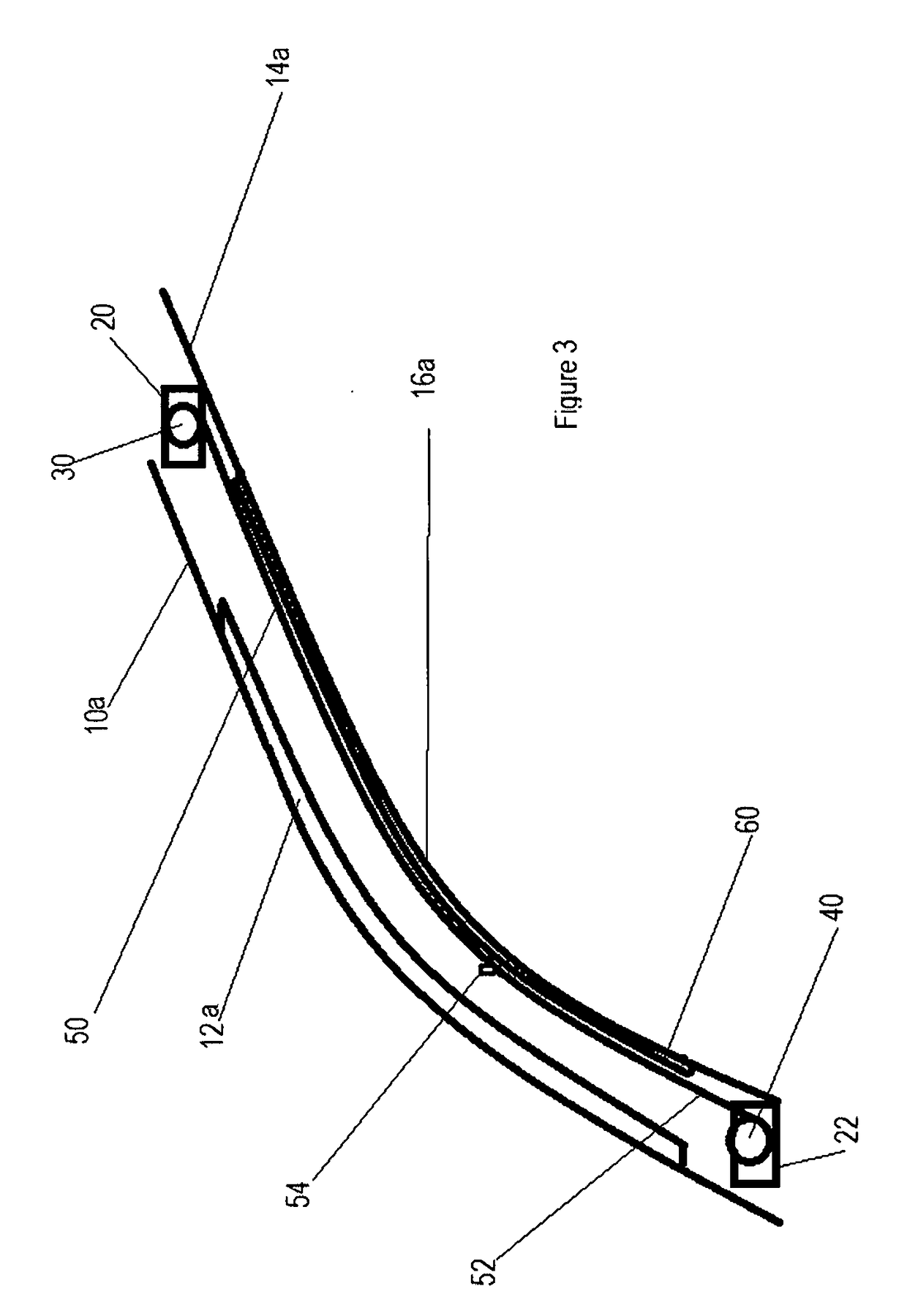
[0020]FIGS. 1-3 show schematically, multiple embodiments of the present invention, as applicable to vehicles, such as Class B motorhome RVs. The following features are[0021]illustrated in those drawings:

[0022]a vehicle 10, having a wall into which an inclined window 12 or curved window 12a is mounted (such as a cab-over window in a Class B motorhome), the vehicle typically resting on a generally horizontal plane of reference, such as a road or the ground,[0023]a window shroud 14 or 14a, typically mounted inside of vehicle 10 and in close proximity to window 12 or 12a, respectively, the distance therebetween forming a wall thickness for vehicle 10,[0024]an opening 16 or 16a in the window shroud, that opening generally corresponding in location and dimension to the location and dimension of corresponding window 12 or 12a, respectively,[0025]an elevational or aesthetic feature 18 of shroud 14, altering the topography of that shroud in certain instances, and thereby changing the wall th...


PUM


Abstract

A motorized shade assembly is provided having a discontinuous web extending between two rollers, one of which is motorized and the other is tensioned or biased toward rotation away from the other roller. The roller motor can be mounted inside of one of the rollers, and the tensioning device, such as a torsion spring, can be mounted inside of the other roller. The web includes a shade portion and a strap portion, with a rigid draw bar at the junction of those portions. Rotation of the rollers causes the strap portion to wrap over one of the rollers as the shade portion unwraps from the other roller. The shade assembly can be positioned between an inclined or curved vehicle window and an interior shroud for the window, such as found with a cab-over window of a Class B motorhome. The draw bar and fasteners connecting the strap to the draw bar facilitate movement of the shade when in contact with the shroud. Friction reducing tape or surface treatment on the periphery of the window opening in the shroud can also facilitate movement of the shade when in contact with the shroud. Motor actuation can be hardwired to a desired location within the vehicle, or wirelessly controlled by the user, as with an RF device.

Description

BACKGROUND OF THE INVENTION[0001]The present invention relates to motorized window shades, and, more particularly to shades for inclined or curved windows mounted in vehicles, such as recreational vehicles (RVs), especially those windows in cab-over locations of Class B RVs.[0002]A wide variety of window shades have been used. In general, these shades permit the users to selectively cover and uncover some or all of a window opening, as desired to control the amount of light coming into a window and / or to control visibility through the window. For the convenience of the user, and especially where the window is less readily accessible, some prior window shades have been operable via motors. Motorized shades can perform their function well in connection with modest sized, vertical windows in static structures, such as those windows found in traditional residences.[0003]However, motorized shades tend to be more expensive than manually operable shades, and typically require more bulky me...

Claims


Application Information

Patent Timeline
IPC IPC(8): E06B9/72E06B9/44B60J1/20
CPCE06B9/72E06B9/44B60J1/2016B60J1/2019B60Y2200/147B60J1/2025B60J1/2061E04F10/06E04F10/0655E06B9/42E06B9/58E06B9/62E06B9/66E06B2009/405
Inventor DELVECCHIO, THOMAS L.
Owner JAYCO INC
Learn More