
Arcuate motion actuator based on piezo-electric motors

a piezo-electric motor and actuator technology, applied in the direction of generator/motor, cosmonautic vehicle, transportation and packaging, etc., can solve the problems of small power, none of the above publications provide a direct drive between the motor and the fin/flap control, etc., to increase the pre-load, and reduce the volume of the package

Active Publication Date: 2019-03-28
NANOMOTION
View PDF0 Cites 6 Cited by
  • Summary
  • Abstract
  • Description
  • Claims
  • Application Information

AI Technical Summary

Benefits of technology

The present invention is a motion actuator that uses piezoelectric motors for high-performance flap actuation in military applications. This actuator has the following technical effects: extensive travel, high resolution, wide velocity dynamic range, fast response time, superior move and settle performance, compact dimensions, light weight, low volume, high power density, direct drive, high reliability, and no intrinsic magnetic field. Compared to other actuators, this actuator has many advantages such as high performance, design flexibility, and no clutch requirement. The actuator uses standard piezo-electric motors with strengthening measures such as short tips and increased pre-load to manipulate the trade-off between angular velocity and torque. The actuator can operate on a concave surface and has a high duty cycle.

Problems solved by technology

MEMS devices utilizing an electrostatically controllable rolling flap portion provide a large range of motion while consuming a small amount of power.
None of the above publications provide for a direct drive between the motor and the fin / flap control (because traditionally, one or more gears are typically used) or between velocity and torque.

Method used


Image

  • Arcuate motion actuator based on piezo-electric motors
  • Arcuate motion actuator based on piezo-electric motors
  • Arcuate motion actuator based on piezo-electric motors

Examples


Embodiment Construction

[0029]Illustrative embodiments of the invention are described below. In the interest of clarity, not all features / components of an actual implementation are necessarily described.

[0030]While the present arcuate motion actuator or “arc motor” is implementable in a wide variety of applications, as listed above, the actuator will be described with respect to flap actuators, and specifically missile flap applications, herein below.

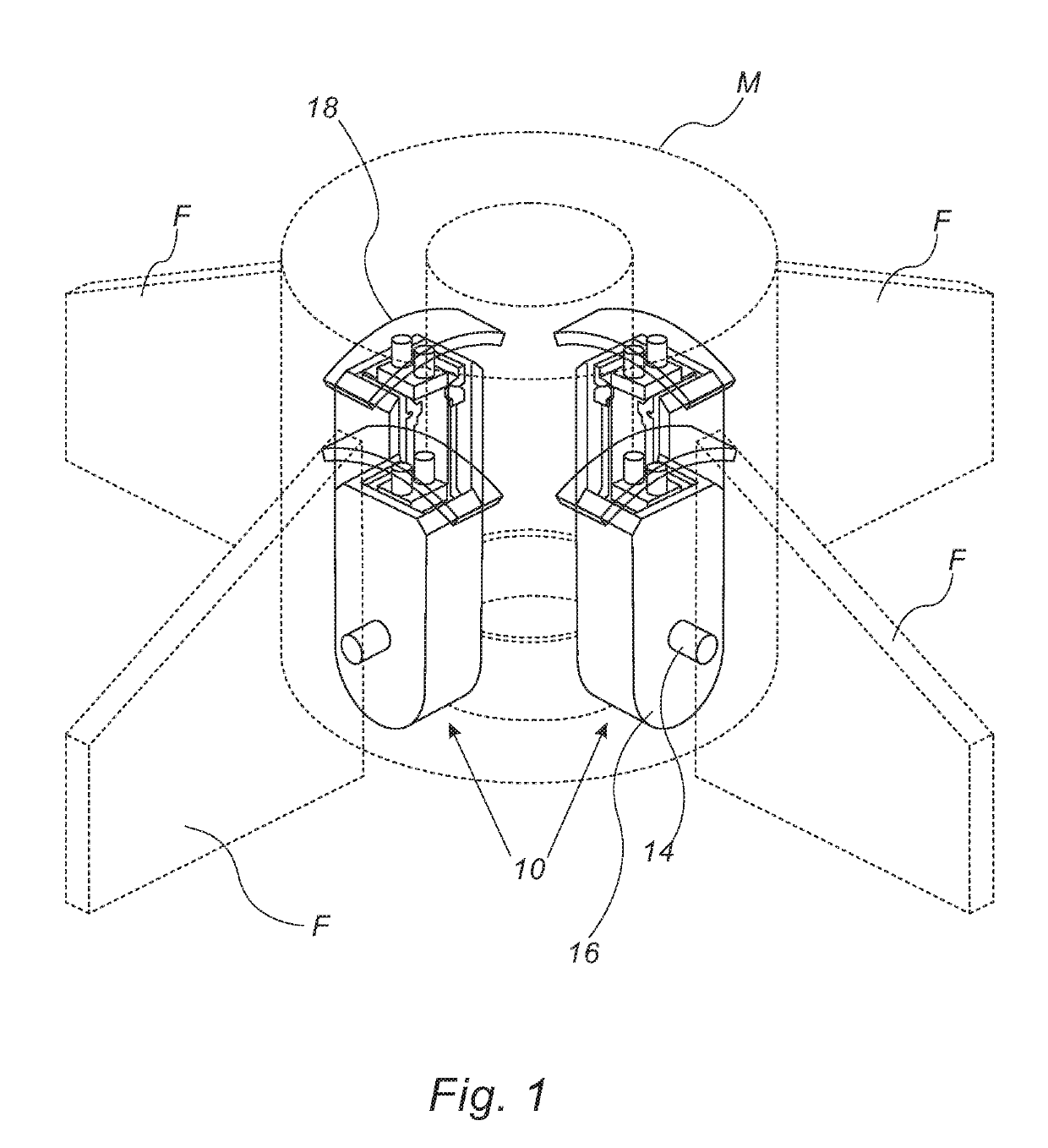
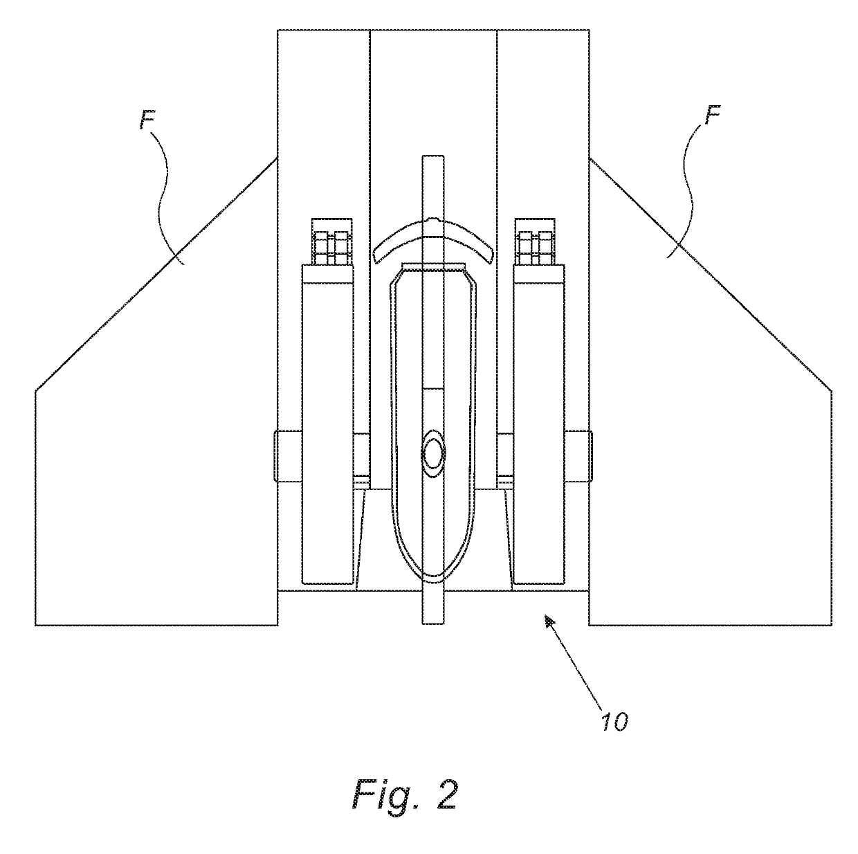
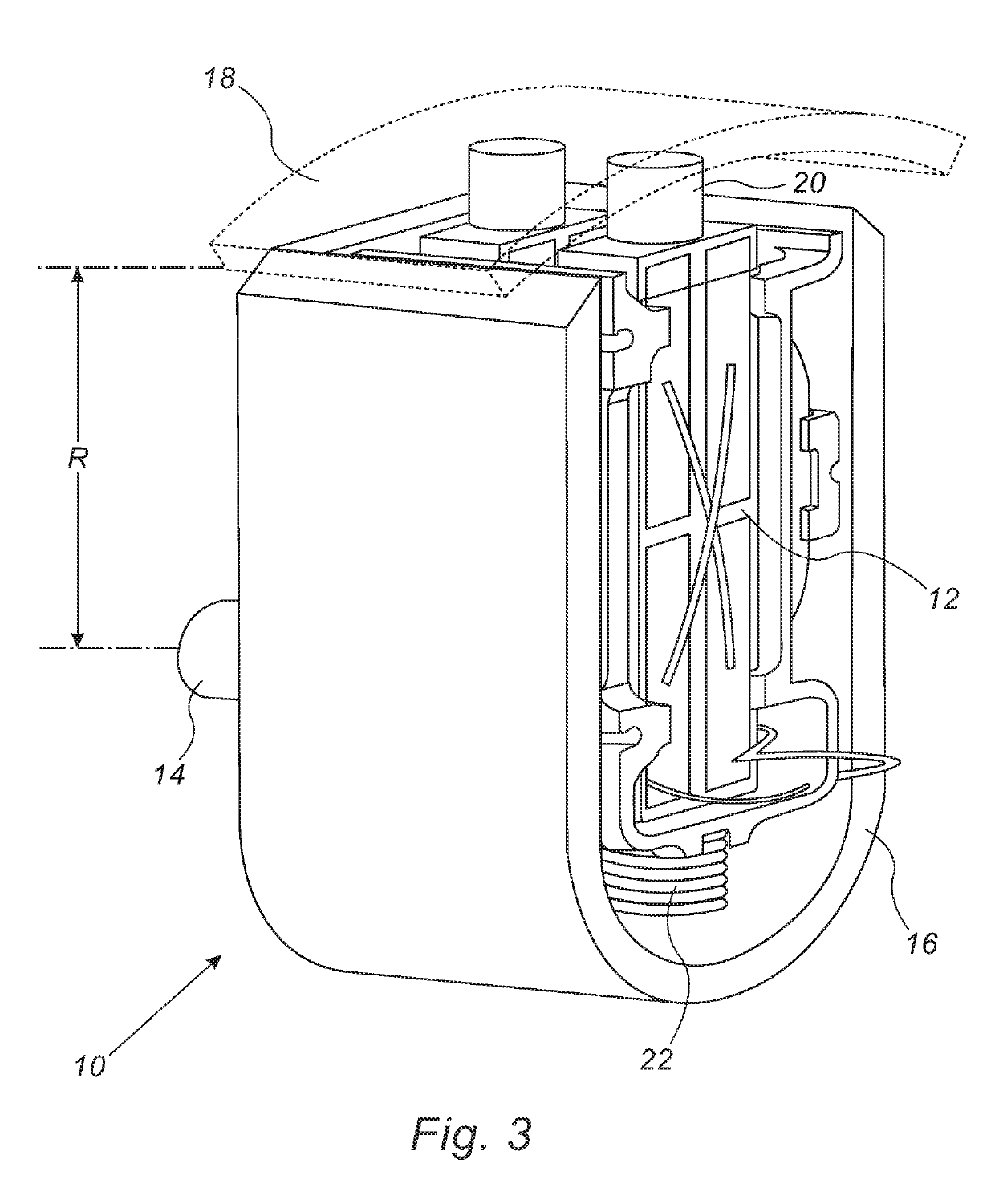
[0031]FIGS. 1-3 show embodiments of a flap actuator 10 of the present invention associated with a flap F of a projectile (e.g. a missile M, a portion thereof shown); and the internal components of the flap actuator including a piezoelectric motor 12; a shaft 14, which is operatively attachable to flap F; a motor housing 16; and a static arcuate member 18, which operatively interfaces with the piezoelectric motor. Piezoelectric motor 12 has associated therewith, or as a part thereof, a nub 20, interfacing with static arcuate member 18; and a biasing member such...


PUM


Abstract

A flap actuator for adjusting the orientation of a flap or the like, the actuator. The actuator includes: a static arcuate member having a radius of curvature; a piezoelectric motor biased to be in operable contact with the static arcuate member; a housing for housing the piezoelectric motor; and a flap orientation shaft operably connecting between the housing and the flap. The distance between the shaft and the static arcuate member is essentially equal to the radius of curvature of the static arcuate member.

Description

FIELD OF THE INVENTION[0001]The present invention relates to motion actuating systems, in particular electromechanical motion actuating systems.BACKGROUND OF THE INVENTION[0002]Fins and other steering surfaces (e.g. ailerons, wings, flaps and rudders) are used to guide and / or maneuver and / or control numerous devices, for example: UAV's, launched projectiles and missiles; optical elements (e.g. to manipulate the angle of mirrors, filters, shutters and prisms); theta-phi (pan and tilt) gimbals; valve control actuators; and safe and arm devices. The flaps are actuated by motors. In the case of rockets, four fins are required.[0003]Examples of devices that can be used for flap actuation are disclosed in: U.S. Pat. No. 5,824,910 (Last, et al., 1998 Oct. 20) entitled “Miniature Hydrostat Fabricated Using Multiple Microelectromechanical Processes”; U.S. Pat. No. 6,069,392 (Tai, et al., 2000 May 30) entitled “Microbellows Actuator”; and U.S. Pat. No. 6,474,593 (Lipeles, et al., 2002 Nov. 5)...

Claims


Application Information

Patent Timeline
Patent Type & Authority Applications(United States)
IPC IPC(8): H02N2/10B64C13/00F42B10/64
CPCH02N2/103B64C13/00F42B10/64B64C13/50B64G1/244B64C9/02
Inventor KARASIKOV, NIR
Owner NANOMOTION
Learn More