Displacement amplifying mechanism and liquid ejecting apparatus using the same
Active Publication Date: 2019-04-04
SEIKO EPSON CORP
3 Cites 0 Cited by
AI-Extracted Technical Summary
Problems solved by technology
However, in the technique of JP-A-7-301354, in a case where the piezoelectric element is rapidly contracted and the large diameter piston is pulled back, the displacement of the small diameter pist...
Benefits of technology
[0046]In this case, it is possible to inhibit the deterioration of the ejecti...
Abstract
An displacement amplifying mechanism that enlarges an amount of displacement of an actuator includes an accommodation chamber in which a liquid is sealed, a first wall portion that forms a wall surface of the accommodation chamber and applies a pressure to the liquid in accordance with displacement of the actuator, and a second wall portion that forms the wall surface of the accommodation chamber and is displaced in a first direction which is a direction away from the accommodation chamber in a state where an elastic force acting in a second direction approaching the accommodation chamber is generated by a pressure of the liquid when the first wall portion applies the pressure to the liquid, in which an area of the second wall portion in contact with the liquid is smaller than an area of the first wall portion in contact with the liquid.
Application Domain
Liquid surface applicatorsInking apparatus +6
Technology Topic
EngineeringActuator
Image
Examples
- Experimental program(14)
Example
[0081]The displacement amplifying mechanism 20A of the first embodiment is configured to include the accommodation chamber 21, a liquid 22, a first wall portion 23, and a second wall portion 24. The accommodation chamber 21 is a hollow portion provided inside the housing 11 as described above and is sealed by the first wall portion 23 and the second wall portion 24. In the accommodation chamber 21, the liquid 22 is sealed.
[0082]The type of the liquid 22 is not particularly limited. The liquid 22 may be any liquid having fluidity. The liquid 22 may be, for example, water, oil, liquid metal, fluorinated inert liquid, and liquid resin, and may be a gel-like fluid such as slime. It is desirable that the accommodation chamber 21 is filled with the liquid 22 in a pressurized state in order to enhance pressure transmission efficiency described later. In addition, it is desirable that the liquid 22 is previously subjected to deforming treatment so as to inhibit generation of air bubbles due to cavitation when the pressure changes. In the displacement amplifying mechanism 20A, for example, an indicator portion for confirming the pressure state of the accommodation chamber 21 may be provided by constituting a portion of the wall portion of the accommodation chamber 21 with a member flexibly deformed according to the pressure of the liquid 22.
[0083]The first wall portion 23 is a wall portion that air-tightly separates the accommodation chamber 21 from the drive chamber 12. An outer peripheral end of the first wall portion 23 is fixed to the housing 11. A first wall surface 23a of the first wall portion 23 faces the liquid 22 of the accommodation chamber 21 and configures to include a portion of the wall surface of the accommodation chamber 21. A second wall surface 23b on a side opposite to the first wall surface 23a is connected to the second end portion 15b of the actuator 15 via a connection portion 14. The first wall portion 23 functions as a diaphragm flexibly deformed in a thickness direction according to the displacement of the actuator 15. In the first embodiment, the first wall portion 23 is formed of a film-shaped member made of rubber. The first wall portion 23 may not be formed of a member made of rubber. The first wall portion 23 may be formed of another resin member, or may be formed of a metal plate.
[0084]The second wall portion 24 is a wall portion that air-tightly separates the accommodation chamber 21 from the outside. An outer peripheral end of the second wall portion 24 is fixed to the housing 11. A first wall surface 24a of the second wall portion 24 faces the liquid 22 of the accommodation chamber 21 and configures to include a portion of the wall surface of the accommodation chamber 21. A second wall surface 24b on a side opposite to the first wall surface 24a is connected to the above-described external load (not shown). The second wall portion 24 functions as a diaphragm flexibly deformed in the thickness direction according to a change in the pressure of the accommodation chamber 21. The second wall portion 24 is formed of a member that generates an elastic force as a restoring force when flexibly deformed. In the first embodiment, the second wall portion 24 is formed of a film-shaped member made of rubber. The second wall portion 24 may not be formed of a member made of rubber, may be formed of another resin member, or may be formed of a metal.
[0085]When the pressure of the liquid 22 in the accommodation chamber 21 is enhanced by displacing the first wall portion 23, the second wall portion 24 is displaced in the first direction D1, which is a direction away from the accommodation chamber 21, in a state where an elastic force acting in the second direction D2, which is a direction approaching the accommodation chamber 21, is generated by the pressure of the liquid 22. The first direction D1 is a direction along the thickness direction of the second wall portion 24 and is a direction toward the second wall portion 24 from the accommodation chamber 21. The second direction D2 is a direction toward a direction opposite to the first direction D1. In the first embodiment, the elastic force acting in the second direction D2 caused by the displacement of the second wall portion 24 is generated as the restoring force against the flexure deformation of the second wall portion 24.
[0086]In the displacement amplifying mechanism 20A, an area S2 where the first wall surface 24a of the second wall portion 24 faces the liquid 22 of the accommodation chamber 21 is smaller than an area S1 where the first wall surface 23a of the first wall portion 23 faces the liquid 22 of the accommodation chamber 21. The area S1 of the first wall portion 23 is an area of a region where the region where the first wall surface 23a faces the liquid 22 is projected in the displacement direction on the virtual plane orthogonal to the displacement direction of the first wall portion 23. Similarly, the area S2 of the second wall portion 24 is an area of a region where the region where the first wall surface 24a faces the liquid 22 is projected in the displacement direction on the virtual plane orthogonal to the displacement direction of the second wall portion 24.
[0087]In the displacement amplifying mechanism 20A, as described above, a difference is provided between the area S1 of the first wall portion 23 and the area S2 of the second wall portion 24. Therefore, according to the principle of Pascal, the amount of displacement Dp2 of the second wall portion 24 is enlarged more than the amount of displacement Dp1 of the first wall portion 23 according to the difference between the areas S1 and S2. In addition, according to the displacement amplifying mechanism 20A, when the actuator 15 expands or contracts, the elastic force in the second direction D2 is generated in the second wall portion 24. Therefore, the displacement of the second wall portion 24 in the second direction D2 when the actuator 15 contracts is assisted by the elastic force thereof, so that the delay of the displacement of the first wall portion 23 is inhibited. Therefore, even in a case where the actuator 15 is contracted at a high speed, the pressure in the accommodation chamber 21 is rapidly lowered due to the response delay of the second wall portion 24, and air bubbles are inhibited from being generated in the liquid 22.
[0088]FIGS. 2 and 3 are explanatory diagrams showing an operation characteristic of the displacement amplifying mechanism 20A verified by experiment of the inventor of the invention. FIG. 2 shows graphs Df and Ds showing changes in amounts of displacement of the first wall portion 23 and the second wall portion 24 with respect to the driving voltage applied to the actuator 15. The one dot chain line graph Df shows the amount of displacement of the first wall portion 23, and the solid line graph Ds shows the amount of displacement of the second wall portion 24. In the displacement amplifying mechanism 20A, it is confirmed that the amount of displacement of each of the first wall portion 23 and the second wall portion 24 linearly increases with respect to increase of the driving voltage. In addition, it is confirmed that the amount of displacement of the second wall portion 24 is larger than the amount of displacement of the first wall portion 23 in accordance with the difference between the areas S1 and S2 (FIG. 1) with respect to the same driving voltage.
[0089]FIG. 3 shows graphs Df and Ds showing changes in displacement velocity of the first wall portion 23 and the second wall portion 24 with respect to the driving voltage applied to the actuator 15. In the graph of FIG. 3, the displacement velocity when displaced in the first direction D1 (FIG. 1) is positive (+) and the displacement velocity when displaced in the second direction D2 (FIG. 1) is negative (−). The one dot chain line graph Vfa and the two dot chain line graph Vfb indicate the displacement velocity of the first wall portion 23. The solid line graph Vsa and the broken line graph Vsb indicate the displacement velocity of the second wall portion 24. In the displacement amplifying mechanism 20A, it is confirmed that the displacement velocity of the second wall portion 24 when displaced in the first direction D1 is increased more than the displacement velocity of the first wall portion 23 in accordance with the difference between the areas S1 and S2, similarly to the amount of displacement. In addition, it is confirmed that the displacement velocity of the second wall portion 24 when displaced in the second direction D2 is increased more than the displacement velocity of the first wall portion 23 at substantially the same rate as when displaced in the first direction D1.
[0090]As described above, according to the displacement amplifying mechanism20A in the first embodiment, it is possible to easily enlarge the amount of displacement of the actuator 15 by using the Pascal principle. In addition, responsiveness of the second wall portion 24 to the displacement of the actuator 15 is enhanced by the elastic force acting in the second direction D2 generated when the second wall portion 24 is displaced in the first direction D1. Additionally, according to the displacement amplifying mechanism 20A of the first embodiment and the displacement generator 10A provided therewith, various operational effects described in the above embodiment can be achieved.
Example
2. Second Embodiment
[0091]With reference to FIG. 4, the configuration of an displacement amplifying mechanism 20B in a second embodiment will be described. FIG. 4 is a schematic diagram showing a configuration of an enlarging generation device 10B provided with the displacement amplifying mechanism 20B according to the second embodiment. The configuration of the displacement generator 10B of the second embodiment is substantially the same as that of the displacement generator 10A of the first embodiment except that the displacement amplifying mechanism 20B of the second embodiment is provided instead of the displacement amplifying mechanism 20A of the first embodiment. The configuration of the displacement amplifying mechanism 20B of the second embodiment is substantially the same as that of the displacement amplifying mechanism 20A of the first embodiment except that a filler 25 is dispersed in the liquid 22.
[0092]The filler 25 is formed of a member in which a material having a compressibility lower than that of the liquid 22 is granulated. The filler 25 may be formed of, for example, metal, resin, ceramics, glass, or the like. According to the displacement amplifying mechanism 20B of the second embodiment, the filler 25 inhibits the pressure applied from the actuator 15 from being absorbed by the compression of the volume of the liquid 22. Therefore, the transmission efficiency of the pressure from the first wall portion 23 to the second wall portion 24 via the accommodation chamber 21 is enhanced, and the responsiveness of the displacement amplifying mechanism 20B to the displacement of the actuator 15 is enhanced. Additionally, according to the displacement amplifying mechanism 20B of the second embodiment and the displacement generator 10B provided therewith, the various operational effects described in the first embodiment and the second embodiment can be achieved.
Example
3. Third Embodiment
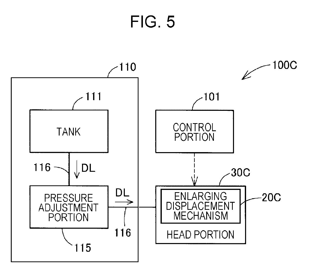
[0093]FIG. 5 is a schematic block diagram showing an overall configuration of a liquid ejecting apparatus 100C according to a third embodiment. The liquid ejecting apparatus 100C is provided with a head portion 30C provided with an displacement amplifying mechanism 20C of the third embodiment, a control portion 101, and a supply portion 110.
[0094]The head portion 30C ejects an ejection liquid DL using the displacement amplifying mechanism 20C of the third embodiment. The ejection liquid DL is, for example, ink having a predetermined viscosity. The operation of the head portion 30C is controlled by the control portion 101. The configuration of the head portion 30C and the configuration of the displacement amplifying mechanism 20C of the third embodiment will be described later.
[0095]The control portion 101 is configured as a computer provided with a CPU and a memory, and realizes various functions for controlling the liquid ejecting apparatus 100C by the CPU reading and executing the control program and command stored in the memory. The control program may be recorded on various non-transitory tangible recording media. The control portion 101 may be configured to include a circuit.
[0096]The supply portion 110 supplies the ejection liquid DL to the head portion 30C. The supply portion 110 is configured to include a tank 111, a pressure adjustment portion 115, and a supply path 116.
[0097]The ejection liquid DL is contained in tank 111. The ejection liquid DL in the tank 111 is supplied to the head portion 30C through the supply path 116 connected to the head portion 30C.
[0098]The pressure adjustment portion 115 is provided in the supply path 116, and adjusts the pressure of the ejection liquid DL supplied to the head portion 30C through the supply path 116 to a predetermined pressure. The pressure adjustment portion 115 is configured to include a pump that sucks the ejection liquid DL from the tank 111, a valve that opens and closes so that the pressure on the head portion 30C side becomes a predetermined pressure, and the like (not shown).
[0099]FIG. 6 is a schematic cross-sectional view schematically showing an internal configuration of a head portion 30C according to the third embodiment. The head portion 30C is provided with a metallic housing 31. The head portion 30C is provided with a nozzle 32, a pressure chamber 33, a supply flow path 35, a drive chamber 40, and an actuator 41 inside the housing 31, in addition to the displacement amplifying mechanism 20C of the third embodiment.
[0100]The nozzle 32 is provided as a through-hole that communicates with the pressure chamber 33 and is open to the outside of the housing 31. In the third embodiment, since the head portion 30C ejects the ejection liquid DL in the direction of gravity, the nozzle 32 is open in the direction of gravity.
[0101]The pressure chamber 33 accommodates the ejection liquid DL ejected from the nozzle 32. The pressure chamber 33 is connected to the supply path 116 of the supply portion 110 via the supply flow path 35 which is a flow path through which the ejection liquid DL flows. The ejection liquid DL is pressure-fed from the supply portion 110 to the pressure chamber 33 through the supply flow path 35. The pressure in the pressure chamber 33 when the ejection liquid DL is not ejected from the nozzle 32 is adjusted to a pressure equal to or lower than the meniscus withstand pressure of the nozzle 32 by the pressure adjustment portion 115 (FIG. 5) of the supply portion 110.
[0102]The drive chamber 40 is provided above the pressure chamber 33 in the direction of gravity with the displacement amplifying mechanism 20C interposed therebetween. The drive chamber 40 accommodates the actuator 41. The actuator 41 changes the volume of the pressure chamber 33 via the displacement amplifying mechanism 20C and causes the pressure chamber 33 to generate pressure for ejecting the ejection liquid DL from the nozzle 32 (details will be described later). In the third embodiment, similarly to the actuator 15 described in the first embodiment, the actuator 41 is formed of a piezo element that expands and contracts. A first end portion 41a in the expansion and contraction direction of the actuator 41 is fixed to the housing 31 via a fixing portion 42.
[0103]The displacement amplifying mechanism 20C has the same configuration as the displacement amplifying mechanism 20B of the second embodiment. The displacement amplifying mechanism 20C is provided with the accommodation chamber 21 filled with the liquid 22, and the first wall portion 23 and the second wall portion 24 configured as a diaphragm flexibly deformed in the thickness direction.
[0104]The accommodation chamber 21 is configured as an airtight hollow space between the drive chamber 40 and the pressure chamber 33. The filler 25 similar to that described in the second embodiment is dispersed in the liquid 22 of the accommodation chamber 21.
[0105]The first wall portion 23 air-tightly separates the drive chamber 40 and the accommodation chamber 21 from each other. The outer peripheral end of the first wall portion 23 is fixed to the housing 31. The first wall surface 23a of the first wall portion 23 forms a portion of the wall surface of the accommodation chamber 21 and faces the liquid 22. The second wall surface 23b of the first wall portion 23 is connected to a second end portion 41b in the expansion and contraction direction of the actuator 41 via a connection portion 43.
[0106]The second wall portion 24 air-tightly separates the pressure chamber 33 and the accommodation chamber 21 from each other. The outer peripheral end of the second wall portion 24 is fixed to the housing 31. The first wall surface 24a of the second wall portion 24 forms a portion of the wall surface of the accommodation chamber 21 and faces the liquid 22. The second wall surface 24b of the second wall portion 24 forms a portion of the wall surface of the pressure chamber 33 and faces the ejection liquid DL. It is desirable that the second wall portion 24 is disposed so that a central portion of the second wall surface 24b faces the nozzle 32.
[0107]In the head portion 30C, the actuator 41 is instantaneously extended, when the first wall portion 23 is displaced as shown by a broken line, the second wall portion 24 is displaced in the first direction D1 as indicated by a broken line by the pressure received from the liquid 22 of the accommodation chamber 21. As a result, the pressure in the pressure chamber 33 is increased to be the meniscus withstand pressure or higher, and the ejection liquid DL is ejected from the nozzle 32.
[0108]Here, the area S2 where the first wall surface 24a of the second wall portion 24 faces the liquid 22 of the accommodation chamber 21 is smaller than the area S1 where the first wall surface 23a of the first wall portion 23 faces the liquid 22 of the accommodation chamber 21. Therefore, similarly to the description in the first embodiment, the amount of displacement Dp2 of the second wall portion 24 is larger than the amount of displacement Dp1 of the first wall portion 23. Therefore, in the head portion 30C, it is possible to easily generate a larger ejection pressure in the pressure chamber 33 by the displacement amplifying mechanism 20C having a simple configuration. In addition, in the head portion 30C, even if a small actuator 41 having a small amount of expansion and contraction deformation is adopted, the amount of displacement of the second wall portion 24 can be compensated by the displacement amplifying mechanism 20C. Therefore, by using the displacement amplifying mechanism 20C, it is possible to downsize the actuator 41 and to downsize the head portion 30C.
[0109]In addition, in the displacement amplifying mechanism 20C, as described in the first embodiment, the second wall portion 24 is displaced in the first direction D1 in a state where an elastic force acting in the second direction D2 is generated. Therefore, the compliance of the displacement of the second wall portion 24 in the second direction D2 when the actuator 41 is displaced in the contracting direction is enhanced by the elastic force. As a result, even if the actuator 41 contracts momentarily, the pressure in the accommodation chamber 21 is lowered, and air bubbles are inhibited from being generated in the liquid 22. Therefore, it is possible to stably drive the head portion 30C. In the liquid ejecting apparatus 100C, since there are cases where the actuator 41 is repeatedly expanded or contracted at a high speed, the merit obtained by such an effect of inhibiting the generation of air bubbles is great.
[0110]In addition, according to the head portion 30C, the response delay of the second wall portion 24 is inhibited as described above, so that the occurrence timing of the negative pressure in the pressure chamber 33 can be inhibited from being delayed from the aimed timing. Therefore, a negative pressure can be generated in the pressure chamber 33 at an appropriate timing after the ejection of the ejection liquid DL from the nozzle 32 is started, so that it is possible to inhibit unnecessary tail of the ejection liquid DL ejected from the nozzle 32 and unnecessary mist generation due to ejection. Therefore, the accuracy of the ejection amount of the ejection liquid DL is enhanced, and deterioration of the flight state of the liquid droplets is inhibited.
[0111]As described above, according to the liquid ejecting apparatus 100C of the third embodiment, by provided with the displacement amplifying mechanism 20C to which the principle of Pascal is applied, the ejection performance of the ejection liquid DL can be enhanced. In addition, the actuator 41 can be downsized, and the head portion 30C can be downsized. Additionally, according to the liquid ejecting apparatus 100C of the third embodiment, various operational effects described in the first embodiment, the second embodiment, and the third embodiment can be achieved.
PUM


Description & Claims & Application Information
We can also present the details of the Description, Claims and Application information to help users get a comprehensive understanding of the technical details of the patent, such as background art, summary of invention, brief description of drawings, description of embodiments, and other original content. On the other hand, users can also determine the specific scope of protection of the technology through the list of claims; as well as understand the changes in the life cycle of the technology with the presentation of the patent timeline. Login to view more.