Numerical controller

Active Publication Date: 2019-04-04
FANUC CORP
View PDF3 Cites 5 Cited by
  • Summary
  • Abstract
  • Description
  • Claims
  • Application Information

AI Technical Summary

Benefits of technology

[0012]The present invention can provide a numerical controller capable of improving the quality of a machi

Problems solved by technology

The disordered steps on the tool paths reduce the quality of the machined workpiece surface.
Consequently, the spline curve does not accurately restore the ideal curve.
Unfortunately, the methods of Japanese Patent Application Laid-Open Nos. 2011-096077 and

Method used


Image

  • Numerical controller
  • Numerical controller
  • Numerical controller

Examples


example

[0041]An Example of this embodiment is described with reference to FIGS. 11 and 12.

(1) Acquisition of Command Point Sequence

[0042]The command point sequence acquisition unit 110 acquires the coordinates of the points A1, A2, A3, A4, A5 and A6 that form a command point sequence output from CAM. In FIG. 11, these existing command points are indicated by a large circle.

(2) Creation of Additional Command Points

[0043]The command point creating unit 120 newly creates additional command points B1, B2 and B3 between the existing command points acquired by the command point sequence acquisition unit 110. In FIG. 11, these additional command points are indicated by a small circle.

(Creation of an Additional Command Point B1)

[0044]The command point creating unit 120 can create the additional command point B1 according to the processes in the following steps 1 to 5.

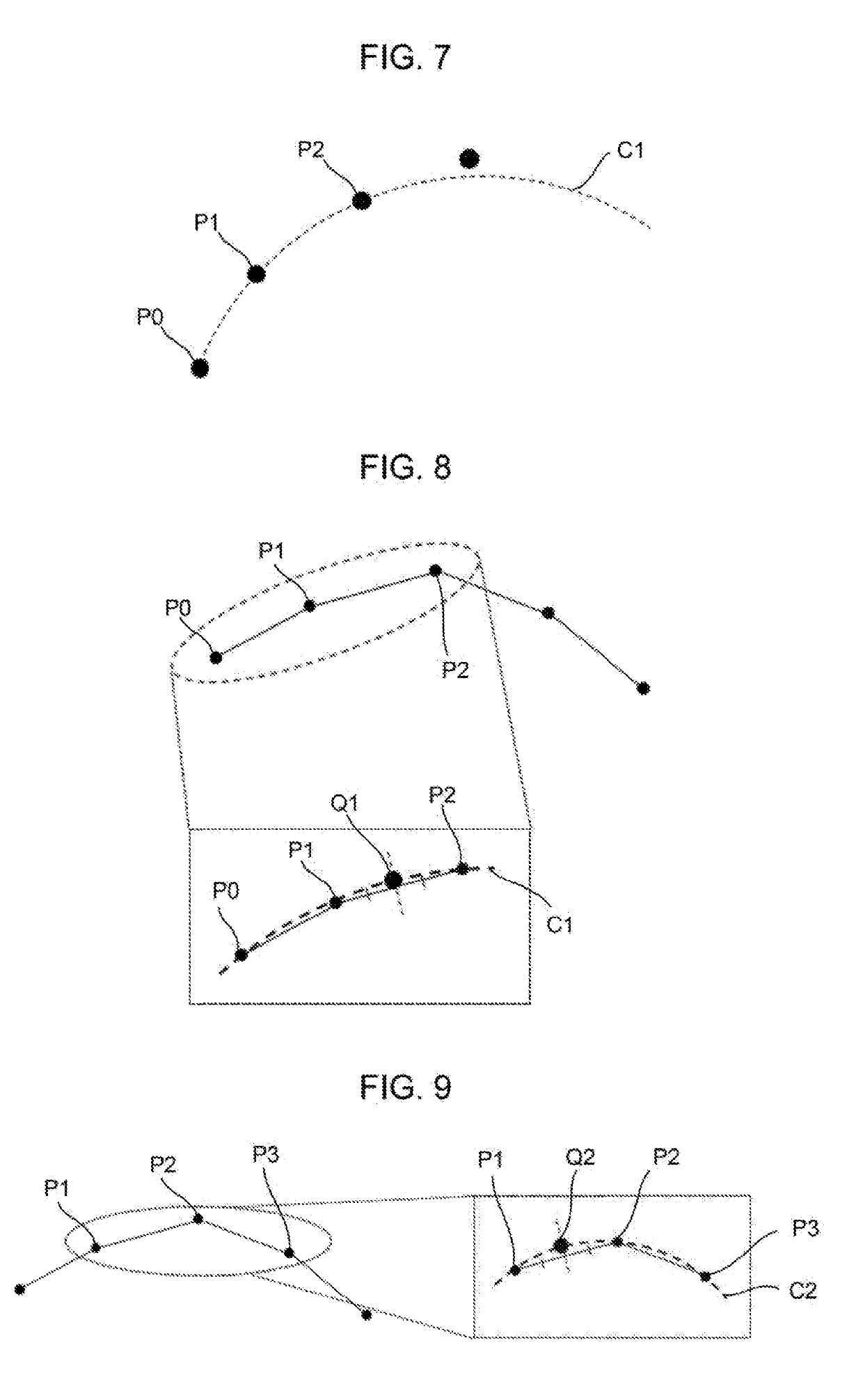
[0045]Step 1: The command point creating unit 120 defines the arc C1 passing through three points, i.e., A1 that is an end point in ...


PUM


Abstract

A numerical controller that creates a tool path from a plurality of command points includes: a command point sequence acquisition unit that acquires an existing command point sequence; a command point creating unit that creates at least one additional command point, based on the existing command point sequence; and an interpolation processing unit that interpolates the existing command point sequence and the additional command point to create the tool path. The command point creating unit outputs, as the additional command point, an intersection point Q1 between an arc C1 passing through consecutive three command points, P0, P1 and P2, in the existing command point sequence and a perpendicular bisector of a line segment whose end points are P1 and P2.

Description

BACKGROUND OF THE INVENTION1. Field of the Invention[0001]The present invention relates to a numerical controller and, in particular, to a numerical controller capable of improving the quality of a machining surface of a workpiece by correctly interpolating command points.2. Description of the Related Art[0002]In a case of creating a program for machining a mold or the like, CAM (computer aided manufacturing) converts a curve (hereinafter, an ideal curve; see the left diagram in FIG. 1) created by CAD (computer aided design) into a point sequence. These points are called command points (see the center diagram in FIG. 1). The ideal curve is converted into the command point sequence to thereby be represented as infinitesimal line segments, and information on between the command points are lost. CNC (computerized numerical control) smooths these infinitesimal line segments output from CAM, thereby creating a tool path made up of a smooth curve (see the right diagram in FIG. 1).[0003]In...

Claims


Application Information

Patent Timeline
IPC IPC(8): G05B19/19
CPCG05B19/19G05B2219/34083G05B2219/35261G05B2219/45044G05B19/41G05B2219/32368G05B19/4103G05B2219/34135Y02P90/02
Inventor KONISHI, KOUKIKAWAMURA, HIROYUKIHANAOKA, OSAMU
Owner FANUC CORP
Why Eureka
Try Eureka