Bone ties and staples for use in orthopaedic surgery

a technology applied in the field of bone ties and staples for use in orthopaedic surgery, can solve the problems of weak compression force, cell death, and disruption of blood supply, and achieve the effect of reducing the number of fractures

Inactive Publication Date: 2019-04-11
APIO IMPLANTS
View PDF3 Cites 11 Cited by
  • Summary
  • Abstract
  • Description
  • Claims
  • Application Information

AI Technical Summary

Benefits of technology

[0014]According to one aspect of the present invention there is provided a surgical bone tie for use in joining abutting bone surfaces for stabilizing, fusing or knitting of the bone together, the tie comprising (or consisting of) first and second pieces each having a proximal end region and a distal end region which define a longitudinal axis therebetween, wherein the distal end regions are each provided with a mounting feature for fixing, or permitting the fixing, of each piece to respective underlying portions of bone, wherein the proximal end regions of each pieces are adapted for engagement together along said axis so that one proximal end region may be accommodated by the other proximal end region to provide a bridge between the respective distal end regions, the engagement permitting one way travel of one piece progressively towards the other so that the bridge length becomes progressively smaller until a desired amount of separation between the distal end regions is obtained, and then a desired compression between the abutting bones is obtained.
[0016]The first piece of the bone tie is preferably an elongate female sleeve member with a hollow cross-section and the second piece of the bone tie is preferably a male member that forms a sliding fit in the female sleeve member. By using an elongate female sleeve member with hollow cross-section, the elongate female sleeve member fully envelops the proximal end region of the male member in use. The female sleeve member therefore shields the ratchet and pawl connection from impingement by soft tissue at the implantation site.
[0017]The pawl preferably comprises a cantilever spring member, a free end of which spring member is biased against the ratchet for sequential engagement with ratchet teeth. By using a cantilever spring the number of moving parts and components is minimized. Use of a cantilever spring can also avoid damage to the pawl or ratchet teeth during compression.

Problems solved by technology

Screw fixation is commonly used but often requires multiple screws to achieve stability, drilling to create a pilot hole which may cause bone necrosis (cell death) and disruption of the blood supply which is crucial for fusion healing.
Current staple designs include static staples that do not allow for compression, and compression staples.
A disadvantage of this design is that compression forces obtained are weak, and the forces may reduce overtime due to material relaxation.
Furthermore staples may cause distraction at the opposite side of bone, causing a gap and potential non-union of the fusion site (see Farr D et al, “A biomechanical comparison of shape memory compression staples and mechanical compression staples: compression or distraction?” Knee Surg.
In addition, the user is unable to select the degree of compression as it is predetermined during the design and manufacture of the staple.
Some memory metals require activation using bespoke devices or machines, which increases cost and surgical time.
There is however no locking mechanism to prevent separation of the limbs under axial loads.
Inevitably there is a tendency for the compression to be released somewhat while the locking member is driven home, which makes the staple less effective.

Method used


Image

  • Bone ties and staples for use in orthopaedic surgery
  • Bone ties and staples for use in orthopaedic surgery
  • Bone ties and staples for use in orthopaedic surgery

Examples


Embodiment Construction

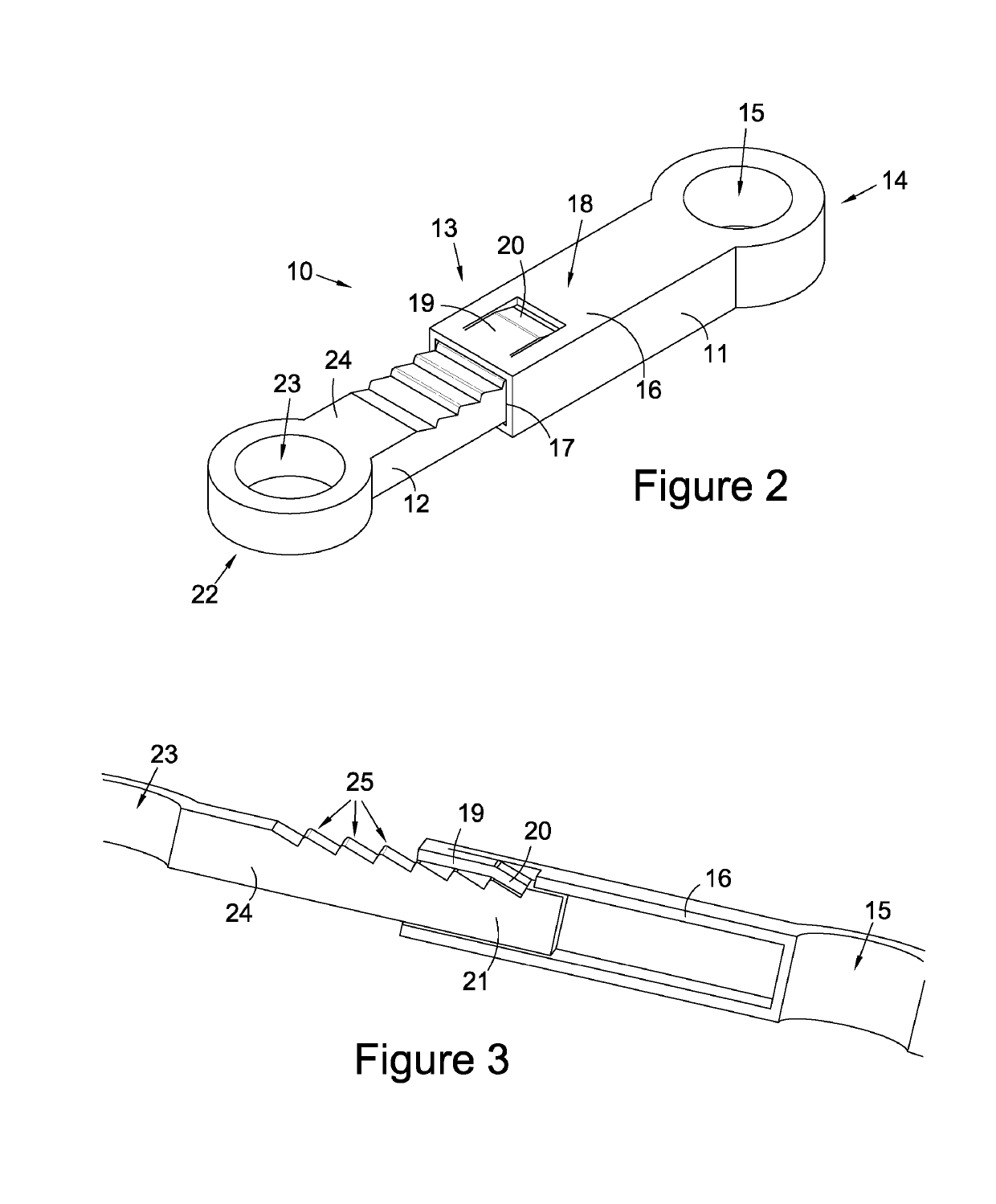
[0041]In FIG. 2 a bone tie 10 is shown. The bone tie consists of a first (female) sleeve member 11 engaged with a second (male) member 12. The sleeve member is elongate and has a proximal end region 13 and a distal end region 14. The distal end region is formed with an annular, vertically opening eyelet 15. A body portion 16 of the sleeve member is elongate with a hollow cross section. In this embodiment the body portion 16 of the sleeve member has a rectangular hollow cross section, however it may have alternative cross sectional shapes, such as a rounded-rectangular hollow cross section. The proximal end 17 of the sleeve member is open to permit entry of the male member. An upper surface 18 of the proximal end is formed with a U-shaped rectilinear cut which defines a tongue 19. The tongue 19 has a distal end region which is formed with an elbow which causes the end 20 to depend from the plane of the tongue. The depending end 20 thus serves as a cantilever sprung pawl (see FIG. 3)....


PUM


Abstract

The present invention concerns the field of orthopaedic surgery, veterinary surgery, and maxillofacial surgery. The invention may find application in other fields such as dentistry or where joining, fusing or stabilising of two bones (or one bone and one prosthetic member) are required. There invention provides a surgical bone tie for use in joining abutting bone surfaces for fusing or knitting of the bone together, the tie comprising (or consisting of) first and second pieces each having a proximal end region and a distal end region which define a longitudinal axis therebetween, wherein the distal end regions are each provided with a mounting feature for fixing, or permitting the fixing, of each piece to respective underlying portions of bone, wherein the proximal end regions of each pieces are adapted for engagement together along said axis so that one proximal end region may be accommodated by the other proximal end region to provide a bridge between the respective distal end regions, the engagement permitting one way travel of one piece progressively towards the other so that the bridge length becomes progressively smaller until a desired amount of separation between the distal end regions is obtained, and the a desired compression between the abutting bones is obtained. The engagement between the proximal end regions preferably comprises a ratchet and pawl connection.

Description

CROSS REFERENCE TO RELATED APPLICATION[0001]The present application is the U.S. national stage application of International Application PCT / GB2017 / 050836 filed Mar. 24, 2017, which international application was published on Sep. 28, 2017 as International Publication WO 2017 / 163080 A1. The International Application claims priority to Great Britain Patent Application 1605087.4 filed Mar. 24, 2016.FIELD OF THE INVENTION[0002]The present invention concerns the field of orthopaedic surgery, veterinary surgery, and maxillofacial surgery. The invention may find application in other fields such as dentistry or where joining, fusing or stabilising of two bones (or one bone and one prosthetic member) are required.BACKGROUND OF THE INVENTION[0003]In orthopaedic surgery, a method of treating a worn and painful joint is to fuse the two facing joint surfaces together. Fusion is where two raw bone surfaces come into contact with each other and biologically join together by the growth of bridging b...

Claims


Application Information

Patent Timeline
Patent Type & Authority Applications(United States)
IPC IPC(8): A61B17/064A61B17/80A61B17/70
CPCA61B17/0642A61B17/8009A61B17/7059A61B17/8023A61B17/8019A61B17/8004
Inventor GORDON, DAVID
Owner APIO IMPLANTS
Why Eureka
Try Eureka