Supercharge Your Innovation With Domain-Expert AI Agents!

Cylinder lock core for a cylinder lock unit

a cylinder lock and core technology, applied in the direction of cylinder locks, keys, locks, etc., can solve the problems of prior locks that have not been constructed and the front region of the key plug in the prior art, so as to prevent the rotation of the key plug and prevent the rotation

Active Publication Date: 2019-04-11
WINLOC
View PDF1 Cites 3 Cited by
  • Summary
  • Abstract
  • Description
  • Claims
  • Application Information

AI Technical Summary

Benefits of technology

The patent is about a cylinder lock unit that uses tumblers to prevent the key from spinning. These tumblers are movable between a position that allows them to be fully contained within the key plug and a position that sticks out and engages with the housing or shell. This prevents the key from spinning and locking the unit.

Problems solved by technology

However, prior locks have not been constructed to include a cylinder lock unit having a housing or shell with a lower part that includes a cylindrical bore accommodating a rotatable key plug with a back region of the key plug having a minimum length of 50% of a total length of the key plug with an adjoining front region having a maximum length of 50% of the total length.
In addition, the prior art does not disclose the front region of the key plug as accommodating at least one side locking mechanism confined entirely within the front region of the key plug that includes a longitudinal row of at least two coded side locking tumblers wherein each side locking mechanism is movable independently of each other with at least three different code positions for each coded side locking tumbler and a plurality of different code combinations for the at least two coded side locking tumblers in each of the longitudinal row.

Method used


Image

  • Cylinder lock core for a cylinder lock unit
  • Cylinder lock core for a cylinder lock unit
  • Cylinder lock core for a cylinder lock unit

Examples


first embodiment

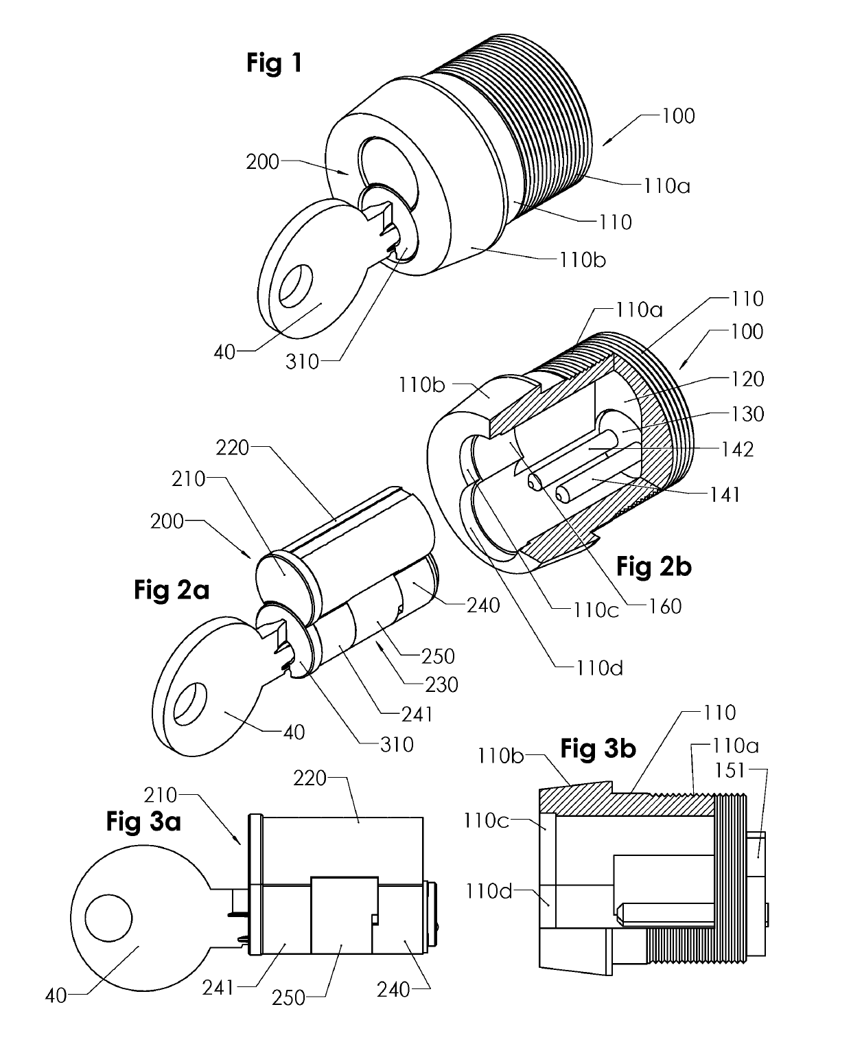
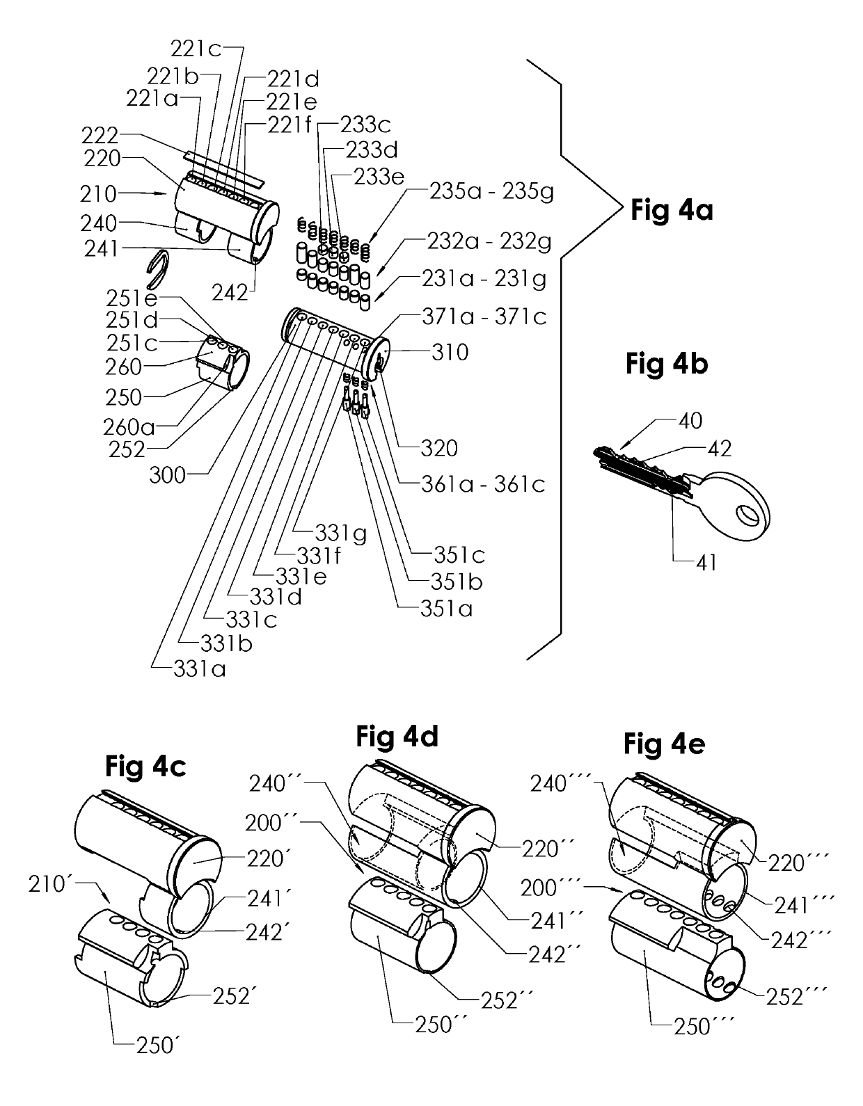
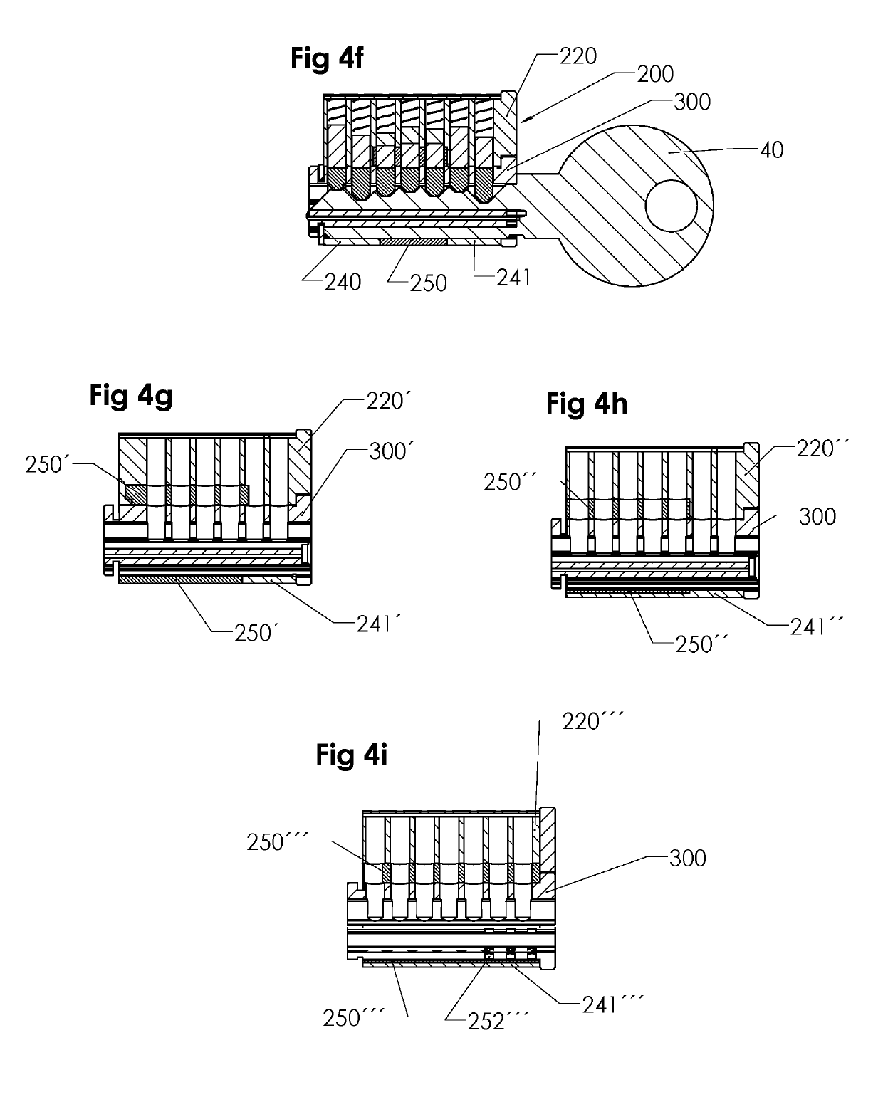
[0075]the invention is shown in FIGS. 1, 2a, 2b, 3a, 3b, 4a, 4b, 4f, 5a, 5b, 5c, 5d and 5e, including a lock unit 100 and an interchangeable cylinder lock core 200 with a rotatable key plug 300 (FIG. 4a).

[0076]The lock unit 100 comprises a cylindrical housing 110 having a threaded rear end portion 110a and a slightly conical front end portion 110b. In a circular hole (not shown specifically) in a rear end wall 120, there is journaled a rotatable plate 130 provided with two parallel rods or prongs 141, 142, which extend in a direction towards the front end portion at the inside of the cylindrical housing 110, and a cam 151 (see FIG. 3b) at the back side of the rear end wall 120. The prongs 141,142 are coupled to the cam 151 via the plate 130, so that a torque can be transferred from the prongs to e.g. a door lock mechanism.

[0077]The lock unit 100 is normally permanently mounted in a door or the like in order to cooperate with a door locking mechanism, as is well known per se. The fro...

second embodiment

[0096]The back end L2 of the key plug 400 is somewhat longer in this second embodiment, and the front end FR2 is shorter (the total length L2+FR2 being the same as in FIG. 5d).

[0097]In a modified version of the second embodiment, shown in FIGS. 8a, 8b, 8c and 8d, the structure is exactly the same as in the one shown in FIG. 7a, etc., except that the number of central locking pins 231a′, . . . 231f′ (FIG. 8c) in the key plug 400 is six rather than seven and the total length of the key plug is a little shorter. Still, the length L2′ of the prong holes is slightly more than half of the length of the key plug.

third embodiment

[0098]In a third embodiment, shown in FIGS. 9, 9a, 9b, 9c, 9d, 9e, 9f, 9g, 9h and FIG. 10, the number of central locking pins is again seven, like in most of the previous embodiments, but the side locking mechanism is different, with only two side locking tumblers, on one side of the key plug 500 only, these two side locking tumblers 551a, 551b cooperating with a relatively short side bar 580 (FIG. 9d). Such a side locking mechanism with a side bar is known per se, but not in the context of interchangeable cylinder lock cores having two relatively long prong holes. The side bar 580 is normally held in a longitudinal recess or groove 243 (see FIG. 9a) by a spring 581 (see FIG. 9d), located between the two side locking tumblers to save longitudinal space, in a position where it projects sideways outside the contour of the key plug 500. In this position, the side bar will register with the corresponding groove 243 in the front end sleeve portion 241 of the shell 200 and thereby effecti...


PUM


Abstract

A cylinder lock unit includes a housing having an upper part and a lower part that includes a cylindrical bore accommodating a rotatable key plug. A back region of the key plug has a minimum length of 50% of a total length of the key plug with an adjoining front region having a maximum length of 50% of the total length. The front region accommodates at least one side locking mechanism confined entirely within the front region of the key plug that includes a longitudinal row of at least two coded side locking tumblers each interacting with the lower part of the housing wherein each side locking mechanism is movable independently of each other with at least three different code positions for each coded side locking tumbler and a plurality of different code combinations for the at least two coded side locking tumblers in each of the longitudinal row.

Description

CROSS-REFERENCE TO RELATED APPLICATION[0001]This Application is a Continuation-In-Part of co-pending U.S. patent application Ser. No. 15 / 617,779 filed on Jun. 8, 2017, which is hereby expressly incorporated by reference into the present application.BACKGROUND OF THE INVENTIONField of the Invention[0002]The present invention relates to a cylinder lock unit which includes a housing or shell having an upper part and a lower part. The lower part of the housing includes a cylindrical bore accommodating a rotatable key plug. A back region of the key plug has a minimum length of 50% of a total length of the key plug with an adjoining front region having a maximum length of 50% of the total length. The front region of the key plug accommodates at least one side locking mechanism confined entirely within the front region of the key plug that includes a longitudinal row of at least two coded side locking tumblers wherein each side locking mechanism is movable independently of each other with ...

Claims


Application Information

Patent Timeline
IPC IPC(8): E05B27/00E05B19/00
CPCE05B27/0078E05B27/0082E05B27/0017E05B27/0007E05B27/0039E05B19/0064E05B9/086
Inventor WIDEN, BO
Owner WINLOC
Features
  • R&D
  • Intellectual Property
  • Life Sciences
  • Materials
  • Tech Scout
  • Unparalleled Data Quality
  • Higher Quality Content
  • 60% Fewer Hallucinations
Learn More