Toggle fixing

a technology of toggle fixing and fixing rod, which is applied in the direction of fastening means, dowels, mechanical equipment, etc., can solve the problems of high frictional force and the inability of toggle fixing to fulfil the function, and achieve the effect of facilitating implementation, and avoiding frictional force generation

Inactive Publication Date: 2019-04-11
FISCHERWERKE ARTUR FISCHER GMBH & CO KG
View PDF7 Cites 9 Cited by
  • Summary
  • Abstract
  • Description
  • Claims
  • Application Information

AI Technical Summary

Benefits of technology

[0009]In order to be able to receive different screws and especially metric screws, there is arranged on the crosspiece at least one counterbearing element made of metal for engagement in the thread of the screw. In particular, the crosspiece has a main body made of plastics, with the result that additional functions, such as, for example, an expansion function in solid building materials (see the specification DE 10 2015 113 332 A1), can be implemented more easily than in metal. In contrast, the counterbearing element made of metal is able, especially in the case of a small area of contact in the thread of a metric screw, to transmit high forces. The counterbearing element is especially planar and especially made of a sheet metal. In particular, the counterbearing element is a stamped and bent component. In order to be able to grip screws having a small thread diameter, the counterbearing is arranged so that it narrows the opening. “Narrow” means that an inside width of the opening, measured transversely with respect to the opening longitudinal axis, is at least at a different location of the opening greater than in the region of the counterbearing element. Relative to the longitudinal extent of the opening, the counterbearing element can be located inside the opening, at the end or in a notional extension thereof on the side of the opening remote from the strip. The “side facing towards the strip” means that side from which the strip extends away from the crosspiece when the strip is perpendicular to the crosspiece, that is to say especially in the installed state of the toggle fixing. What is important, therefore, is not the location at which the strip is attached to the crosspiece, but the direction in which the strip extends. Preferably, however, the strip is attached to the crosspiece also on the side thereof on which the strip extends away from the crosspiece. That side can also be referred to as the “supporting side”, because in the installed state it is typically that side of the crosspiece which comes into contact with the component. The “side remote from the strip” is the side of the crosspiece located opposite the side facing towards the strip.
[0010]The toggle fixing according to the invention is characterised by a plastics body which is arranged on the side of the counterbearing element facing towards the strip and which is movably joined to the crosspiece, especially via a rib or a film hinge, and narrows the opening. The plastics body is especially integral with a main body of the crosspiece. Here too “narrow” means that an inside width of the opening, measured transversely with respect to the opening longitudinal axis, is at least at a different location of the opening greater than in the region of the plastics body. Preferably the plastics body narrows the opening to a greater extent than does the counterbearing element. The reverse case is also a possibility, however. The plastics body is especially arranged in such a way that, prior to the insertion of a screw into the opening, it is either already in contact with the counterbearing element or its distance from the counterbearing element is so small that it makes contact with the counterbearing element at the latest when the screw finds purchase on the counterbearing element. “Movably” means a resilient or resilient-plastic deformation of the rib or the film hinge in such a way that, on insertion of a screw, the plastics body moves in the direction of or with the counterbearing element. The plastics body has the effect that the screw, on being screwed in, is able to press the counterbearing element obliquely away via

Problems solved by technology

It has been found, however, that if the crosspiece and the counterbearing element are rigidly constructed, it can happen in the case of some screws that the end of the counterbearing element facing towards the screw does not adapt to the geometry of the screw like a spring tongue, but instead bears again

Method used


Image

  • Toggle fixing
  • Toggle fixing
  • Toggle fixing

Examples


Embodiment Construction

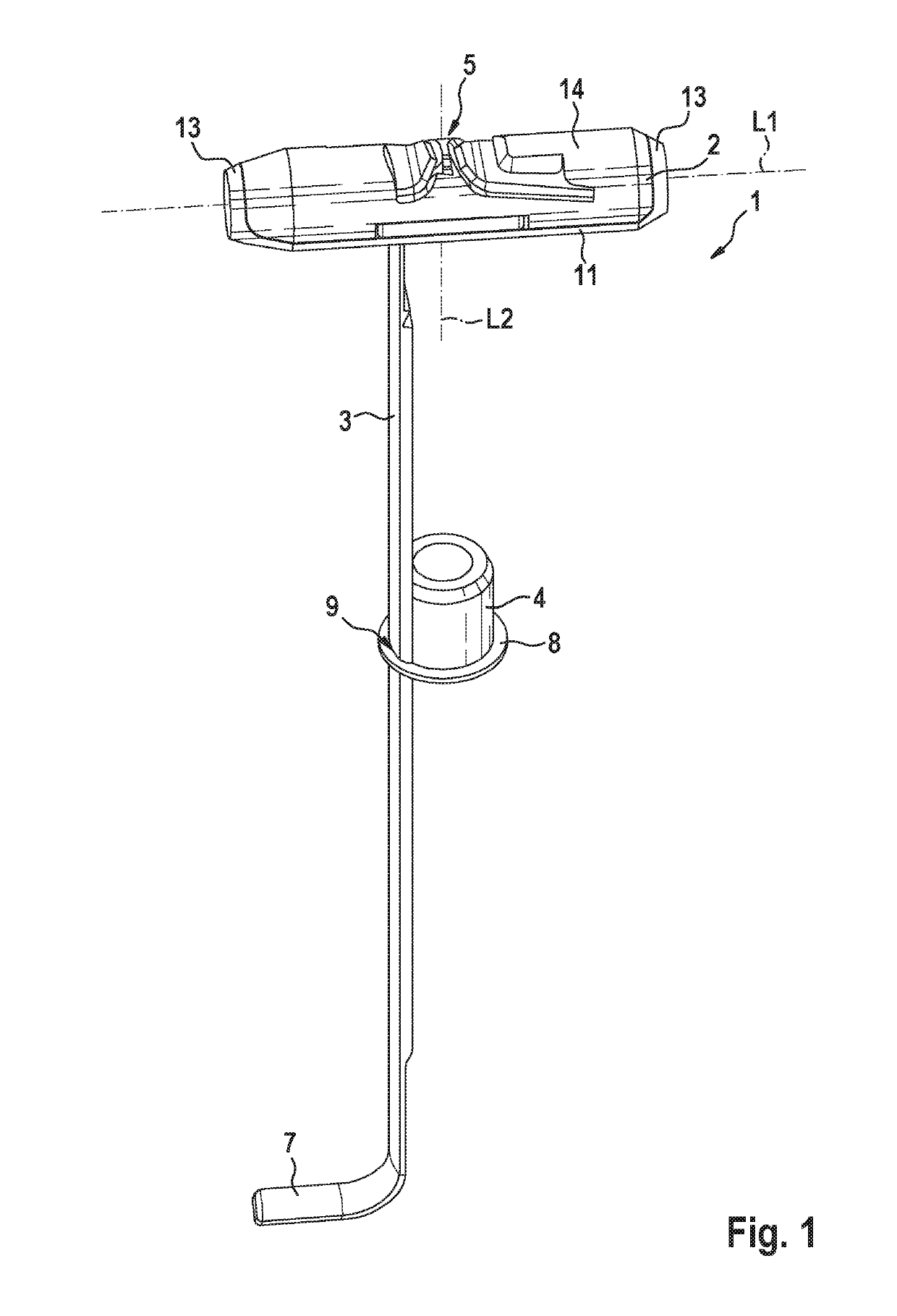
[0021]The toggle fixing 1 according to the invention, shown in the Figures, for fixing an article (not shown) to a thin-walled component, for example a plasterboard panel (not shown), has a substantially cylindrical crosspiece 2, a strip 3 integrally joined to the crosspiece 2, and a sleeve 4 made of plastics which is arranged on the strip 3.

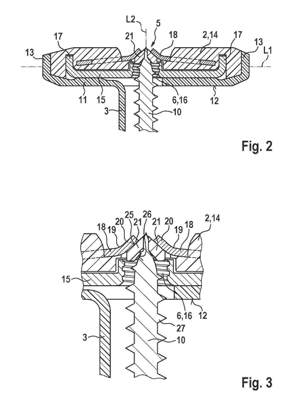
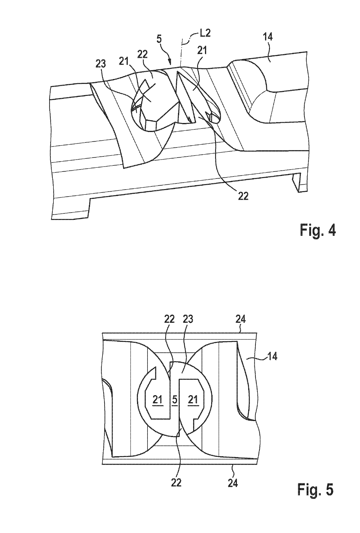
[0022]The crosspiece 2 serves for engaging behind the thin-walled component. It extends along a crosspiece longitudinal axis L1 and has in the centre an opening 5 having an internal thread 6 (see FIGS. 2 and 3), which will be discussed in greater detail hereinbelow. The opening 5 extends along an opening longitudinal axis L2 which runs perpendicularly to the crosspiece longitudinal axis L1. In other words, the opening 5 passes transversely through the crosspiece 2. The strip 3 is attached to the crosspiece 2 next to the opening 5 and in the relaxed state (not shown) extends parallel to the opening longitudinal axis L2, that is to say perpendicul...


PUM


Abstract

A toggle fixing for fixing an article to a thin-walled component, having a crosspiece and a strip for holding the crosspiece during mounting, wherein the crosspiece has an opening for receiving a screw, with two counterbearing elements made of metal for better hold of the screw. In order to prevent certain screws from becoming jammed between the counterbearing elements, the a plastics body is arranged on each of the counterbearing elements on the side thereof facing towards the strip, which plastics body is movably joined to the crosspiece and narrows the opening.

Description

CROSS-REFERENCE TO RELATED APPLICATIONS[0001]This application claims priority under 35 USC § 119 to German Patent Application No. 10 2017 123 655.4, filed on Oct. 11, 2017, the entire disclosure of which is incorporated herein by reference.TECHNICAL FIELD[0002]The invention relates to a toggle fixing.BACKGROUND ART[0003]A generic toggle fixing is known from the specification DE 10 2015 116 421 A1. The toggle fixing is used for fixing an article to a thin-walled component, for example to a plasterboard panel, as used in dry walling for producing walls and for cladding ceilings. A “thin-walled” component can, however, also be the wall of a vertically perforated brick or the wall of an item of ceramic sanitaryware, this list not being exhaustive. In the installed state, the rear side of the component is usually not accessible, but there is a cavity behind the component. If the component is, for example, a plasterboard panel and an article is to be fixed thereto, first of all a hole is ...

Claims


Application Information

Patent Timeline
IPC IPC(8): F16B13/08
CPCF16B13/0808
Inventor DALY, AARON
Owner FISCHERWERKE ARTUR FISCHER GMBH & CO KG
Why Eureka
Try Eureka