Portable Toe Angle Measurement Apparatus and Method

a measurement apparatus and toe angle technology, applied in the direction of measuring devices, instruments, using optical means, etc., can solve the problems of small impact of laser emitter calibration discrepancies on measurement accuracy, and achieve the effects of less cost, small impact on measurement accuracy, and large distan

Active Publication Date: 2019-04-11
SCHWARZ DANIEL +1
View PDF0 Cites 0 Cited by
  • Summary
  • Abstract
  • Description
  • Claims
  • Application Information

AI Technical Summary

Benefits of technology

[0007]The primary advantage of this axle alignment system is that it only requires one laser emitter. Since the same laser emitter is used to take measurements on both ends of the axle in question, any error in parallelism within the laser emitter assembly is negated when the laser is flipped 180 degrees to measure the opposite end of the axle. The laser emitter error would be repeated in opposite directions to create a net zero error. Therefore, laser emitter calibration discrepancies produce little impact on the measurement accuracy. Additionally, a system that utilizes a single laser emitter is less costly than a system which relies on multiple lasers.
[0008]Another advantage of this toe measurement system is the large distance between the laser emitter and the laser target. The further the laser beam travels, the more sensitive the measurement scale is to angular deviation of the steer wheels. At a laser beam length of 285″, the toe angle precision is ±0.0125 degrees when the target scale demarcations are at 1 / 16″ increments. This allows the user to align the axle with greater precision than if the beam was projected a shorter distance.
[0009]Yet another advantage of this axle alignment system is that the laser emitter and targets are constrained using reliable constraints. Precisely machined surfaces on the laser emitter and targets are mated with precisely machined surfaces on the truck reference features. All degrees of freedom between the alignment apparatus and vehicle are completely constrained with tight clearances between mating features. These reliable references and constraints produce measurements that are both accurate and repeatable.

Problems solved by technology

Therefore, laser emitter calibration discrepancies produce little impact on the measurement accuracy.

Method used


Image

  • Portable Toe Angle Measurement Apparatus and Method
  • Portable Toe Angle Measurement Apparatus and Method
  • Portable Toe Angle Measurement Apparatus and Method

Examples


Embodiment Construction

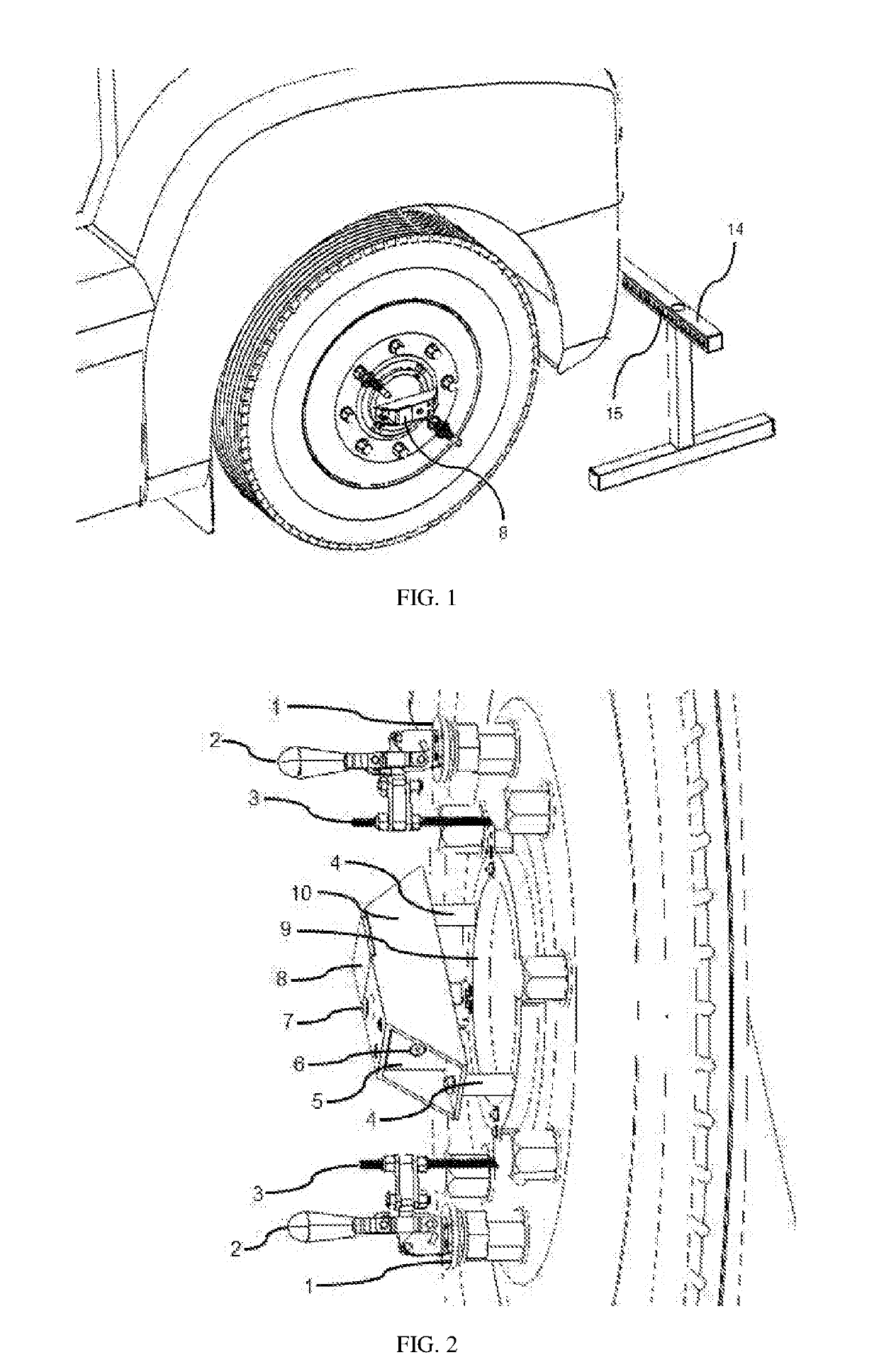
[0015]The preferred embodiment of the laser emitter assembly is illustrated by FIG. 1 and FIG. 2. Clamp nut 1 is threaded onto a lug of the steer wheel of interest. Toggle clamp 2 is constrained to clamp nut 1 with a weld between the flange ring of clamp nut 1 and the mounting base of toggle clamp 2. The flange ring swivels freely, allowing toggle clamp 2 to be rotated relative to clamp nut 1 which is affixed to the wheel lug. Clamp bolt 3 is fastened to the end of the toggle clamp 2 armatures. Clamp bolt 3 presses the wheel bore reference features of steer wheel laser base 9 into the center bore of the steer wheel. Spacers 4 are constrained perpendicular to steer wheel laser base 9 with threaded fasteners. Laser tube 10 is constrained on top of the spacers 4 with threaded fasteners. Laser emitter housing 5 is constrained to the laser tube 10 with threaded fasteners. Laser emitter 6 is press fit into a precision bore in the front of the laser emitter housing 5. The laser emitter 6 i...


PUM


Abstract

A portable laser emitter, laser target, and method for measuring the toe angle of a commercial truck steer axle are disclosed. The laser emitter is mounted to the wheel of a truck steer axle while the laser target is placed in front of the truck. Measurements are taken of the laser dot position on the target with the emitter mounted at either end of the steer axle. The process is then repeated with the target positioned behind the truck. The measurements taken from either end of the steer axle with both front and rear target positions are compared to determine the toe angle of the steer axle.

Description

CROSS-REFERENCE TO RELATED PRIOR APPLICATIONS[0001]This application claims the filing date of provisional patent application Ser. No. 62 / 568,516 filed 10-5-2017 by the present inventors. This application expands the concepts of non-provisional patent application Ser. No. 15 / 296,260 filed Oct. 18, 2016 by the present inventors to include toe angle alignment for steer axles.BACKGROUND[0002]The following table indicates prior art that appears to be relevant to the invention disclosed:U.S. PatentsPatent NumberKind CodeIssue DatePatentee8,401,236B2Mar. 19, 2013Kassouf et al.7,913,404B1Mar. 29, 2011Smith7,661,198B2Feb. 16, 2010Hara6,799,376B1Oct. 5, 2004Voeller et al.6,522,400B1Feb. 18, 2003Horn6,082,011Jul. 4, 2000Philips, III5,675,408Oct. 7, 1997Samuelsson et al5,367,778Nov. 29, 1994O'Hara5,313,710May 24, 1994Wakamori et al.5,157,838Oct. 27, 1992Sims4,500,201Feb. 19, 1985Lill3,181,248May 4, 1965Manlove2,532,593Dec. 5, 1950Bender et al.[0003]The commercial trucking industry's profit marg...

Claims


Application Information

Patent Timeline
Patent Type & Authority Applications(United States)
IPC IPC(8): G01B11/27
CPCG01B11/27G01B11/2755G01B2210/16G01B2210/303
Inventor SCHWARZ, DANIELSCHWARZ, HENRY
Owner SCHWARZ DANIEL
Why Eureka
Try Eureka