No/low-wear bearing arrangement for a knob system

Active Publication Date: 2019-04-11
GRAYHILL
View PDF3 Cites 4 Cited by
  • Summary
  • Abstract
  • Description
  • Claims
  • Application Information

AI Technical Summary

Benefits of technology

[0005]The present disclosure allows for a smooth turning device without extra unintended horizontal displacement, along the X- or Y-axis, or vertical displacement, along the Z-axis. The present disclosure includes a bearing system that provides the device with long rotational life and low friction so detents in the movement of the knob can be felt by the user. If the primary rotation is around the Z-axis, the present disclosure restricts rotation about

Problems solved by technology

The effect of loose tolerances associated with plastic parts and increased wear may be uni

Method used


Image

  • No/low-wear bearing arrangement for a knob system
  • No/low-wear bearing arrangement for a knob system
  • No/low-wear bearing arrangement for a knob system

Examples


Embodiment Construction

[0018]Detailed embodiments of devices and methods are disclosed herein. However, it is to be understood that the disclosed embodiments are merely exemplary of the devices and methods, which may be embodied in various forms. Therefore, specific functional details disclosed herein are not to be interpreted as limiting, but merely as a basis for the claims as a representative example for teaching one skilled in the art to variously employ the present disclosure.

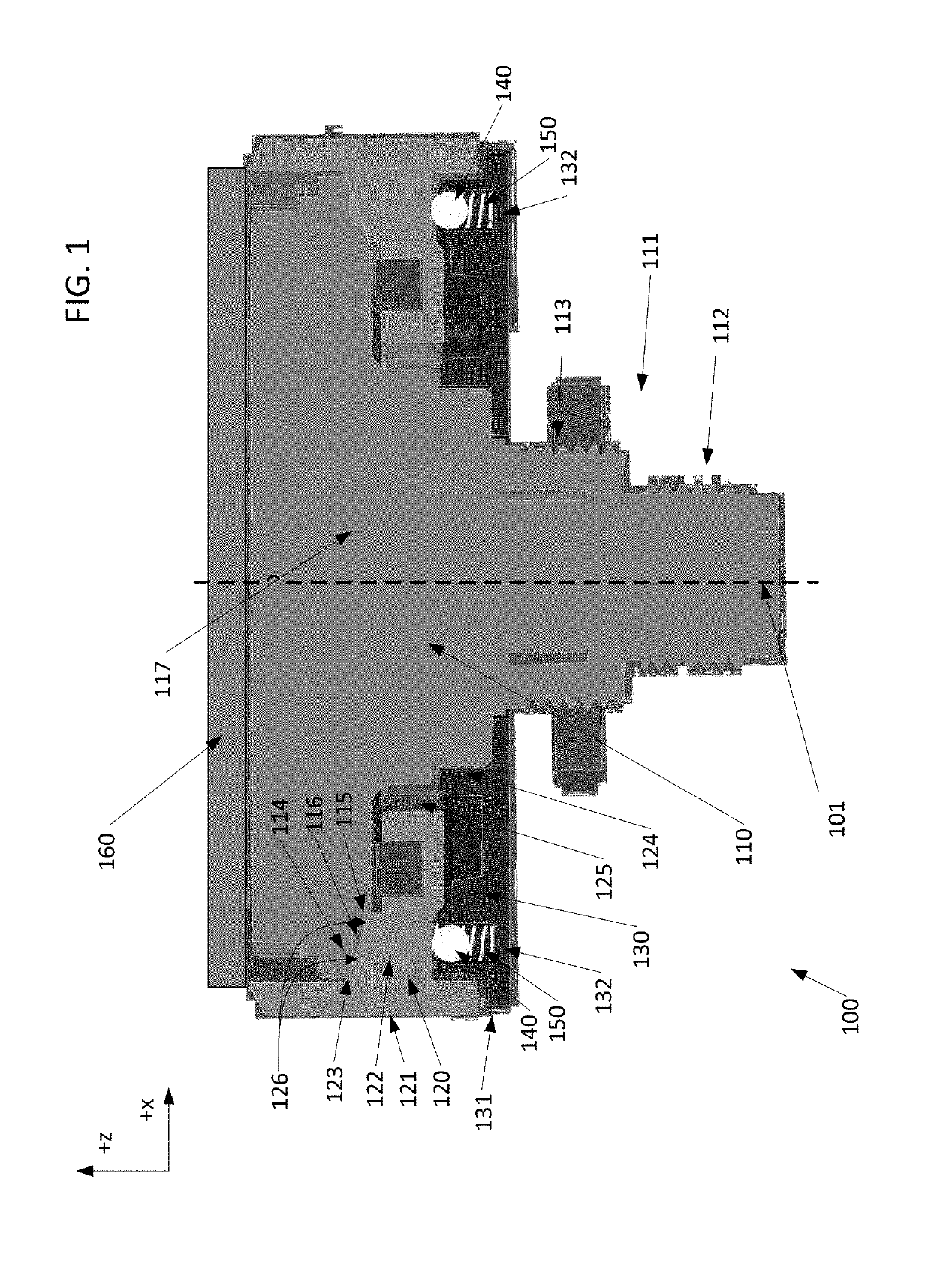
[0019]The present application relates to knob systems for electronic devices. Knob systems generally receive user input through user interaction with the knob system, thus allowing the user to communicate with the electronic device the knob system is configured to relay information to. Knob systems can be configured to rotate in either a clockwise or counterclockwise direction, and can optionally be configured to receive an input via a press, which may be a user depression in the Z-direction perpendicular to the X-Y plane in whi...


PUM


Abstract

The present disclosure is directed to knob systems and methods to permit a smooth turning user input device that minimizes unintended horizontal displacement, along the X- or Y-axis, or unintended vertical displacement, along the Z-axis. The disclosed knob system may achieve this goal through the use of a back plate, a knob and a main housing extending through the knob and the back plate, the back plate comprises a plurality of Z-stop bearings, comprising a plurality of Z-stop balls and a plurality of Z-support springs, wherein the Z-stop bearings are in contact with the back plate and are configured to separate the knob from the back plate when the main housing is depressed in a vertical direction and wherein each of the plurality of Z-stop balls are attached to one of the plurality of Z-support springs, the Z-support springs bias the Z-stop ball against the knob.

Description

PRIORITY CLAIM[0001]This application is a non-provisional of, and claims the benefit of and priority to U.S. Provisional Patent Application No. 62 / 568,854, filed Oct. 6, 2017, incorporated by reference herein in its entirety.BACKGROUND[0002]The present application generally relates to knob systems; more specifically the present application relates to systems and methods for implementing knob movement with reduced wear on the internal arrangements and devices related thereto.[0003]A typical knob system is designed to slide or rotate in the X-, Y-, and Z-directions. To facilitate the movement of the knob system, bearings may be used between contacting parts to provide a reduced friction environment between the parts that would have otherwise contacted. A bearing is implemented in a knob system to allow for smooth movement in the directions where knob movement is guided by the bearing. Bearings also allow for limited wear of moving parts to increase the life of moving components. Howev...

Claims


Application Information

Patent Timeline
IPC IPC(8): H01H19/14H01H19/11
CPCH01H19/14H01H19/11H01H25/06H01H2003/0293H01H2003/326H01H2229/064
Inventor DOOLEY, KEVIN
Owner GRAYHILL
Why Eureka
Try Eureka