Substrate for inkjet head, inkjet head, and inkjet printing apparatus

Active Publication Date: 2014-07-03
CANON KK
View PDF1 Cites 14 Cited by
  • Summary
  • Abstract
  • Description
  • Claims
  • Application Information

AI Technical Summary

Benefits of technology

[0012]In view of the above, the present invention is made. An object of the present invention is to provide a substrate for an inkjet head, an inkjet head, and

Problems solved by technology

However, heating resistors are occasionally subjected to physical action such as the impact of cavitation caused by ink foaming, shrinkage, and defoaming.
Further, in a case where ink reaches the heating resistors, the heating resistors are occasionally subjected to chemical action of the ink.
In a case where this phenomenon spreads, the protection film cannot play the original role and the other heating resistors are also ruptured soon.
However, in a c

Method used


Image

  • Substrate for inkjet head, inkjet head, and inkjet printing apparatus
  • Substrate for inkjet head, inkjet head, and inkjet printing apparatus
  • Substrate for inkjet head, inkjet head, and inkjet printing apparatus

Examples


Example

First Embodiment

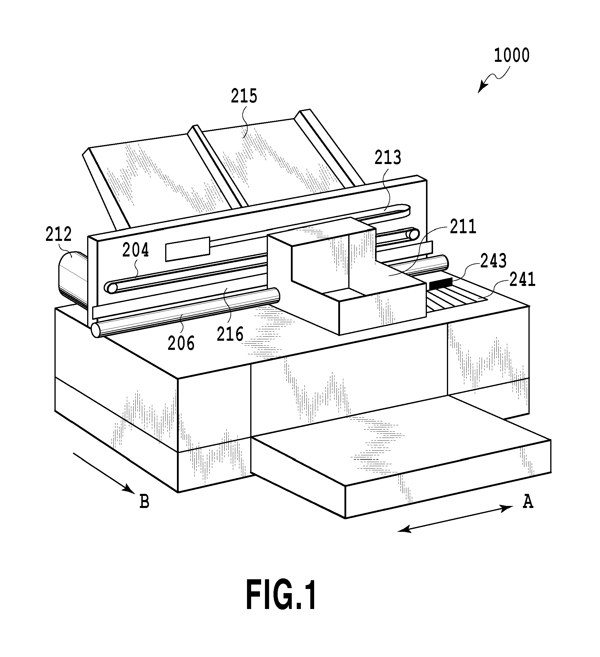
[0033]FIG. 1 is a perspective view showing an inkjet printing apparatus of the present embodiment. The inkjet printing apparatus 1000 includes a carriage 211 for accommodating therein an inkjet print head unit 410. In the inkjet printing apparatus 1000 of the present embodiment, the carriage 211 is guided along a guide shaft 206 so that the carriage 211 can move in a main scan direction shown by an arrow A. The guide shaft 206 is disposed to extend in a width direction of a print medium. Accordingly, an inkjet print head mounted in the carriage 211 performs printing while performing a scan in a direction crossing a conveyance direction in which the print medium is conveyed. As described above, the inkjet printing apparatus 1000 is a so-called serial-scan type inkjet printing apparatus which prints an image by moving the print head 1 in the main scan direction and conveying the print medium in a sub-scan direction.

[0034]The carriage 211 is penetrated and supported by ...

Example

Second Embodiment

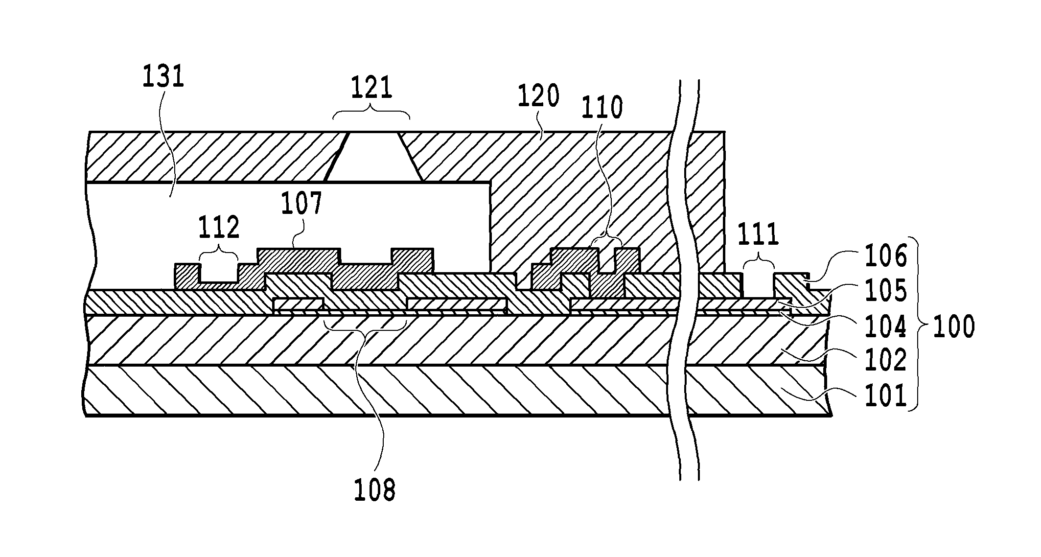
[0070]FIG. 9A is a plan view schematically showing a fuse section 112 of the present embodiment, and FIG. 9B is a cross-sectional view of a substrate taken along line IXB-IXB of FIG. 9A. FIGS. 9C to 9F are explanatory views schematically showing a method for manufacturing an inkjet head of the present embodiment.

[0071]Steps performed to reach a state shown in FIG. 9C are identical to those of the above embodiment. Next, a Ta layer as an upper protection film 107a is formed on a protection layer 106 by sputtering so that the upper protection film 107a has a thickness of about 250 nm.

[0072]Next, dry etching is performed by the photolithography method to partially remove the upper protection film 107a including portions 112a to be blown of the fuse sections so that a shape shown in FIG. 9D is formed. Next, a Ta layer as an upper protection film 107b is formed on the upper protection film 107a by sputtering so that the upper protection film 107b has a thickness of about...

Example

Third Embodiment

[0074]FIG. 10A is a schematic view showing a fuse section of the present embodiment. FIG. 10B is a cross-sectional view of a substrate taken along line XB-XB of FIG. 10A. FIGS. 10C to 10F are schematic views illustrating a method for manufacturing an inkjet head of the present embodiment. In the present embodiment, an upper protection film 107 is formed of two layers, that is, an upper protection film 107c having a thickness of 50 nm and an upper protection film 107d having a thickness of 250 nm. The upper protection film 107c and the upper protection film 107d are formed in substantially the same pattern. Portions 112a to be blown of the fuse sections are formed by removing the upper protection film 107d and formed of only the upper protection film 107c.

[0075]The upper protection film 107c is formed of Ta, and the upper protection film 107d is formed of a platinum group element (Ir in this case).

[0076]In a case where a short circuit 200 occurs, since a voltage is c...


PUM


Abstract

There are provided a substrate for an inkjet head, an inkjet head, and an inkjet printing apparatus wherein in a case where current is carried through a protection layer for heating resistors, electrical connection to its periphery is prevented without fail. The substrate for the inkjet head includes a first protection layer disposed to cover a heating resistor layer and having an insulation property and a second protection layer disposed to contact the first protection layer and having conductivity. The second protection layer includes a plurality of individual sections provided to correspond to the plurality of heating resistors, a common section connecting the plurality of individual sections, and fuse sections connecting the individual sections and the common section, the fuse sections being formed to be thinner than the individual sections.

Description

BACKGROUND OF THE INVENTION[0001]1. Field of the Invention[0002]The present invention relates to a substrate for an inkjet head, an inkjet head, and an inkjet printing apparatus, and particularly relates to a substrate for an inkjet head, an inkjet head, and an inkjet printing apparatus wherein the insulation property of a protection layer is checked.[0003]2. Description of the Related Art[0004]An inkjet printing apparatus needs to continue to eject as large an amount of ink as possible with one heating resistor. However, heating resistors are occasionally subjected to physical action such as the impact of cavitation caused by ink foaming, shrinkage, and defoaming. Further, in a case where ink reaches the heating resistors, the heating resistors are occasionally subjected to chemical action of the ink.[0005]There is a case where in order to protect the heating resistors from the above physical and chemical actions, a protection layer for protecting the heating resistors is provided....

Claims


Application Information

Patent Timeline
IPC IPC(8): B41J2/14
CPCB41J2/14129B41J2/14112
Inventor HATSUI, TAKUYAISHIDA, YUZURUSHIBATA, KAZUAKIYASUDA, TAKERU
Owner CANON KK
Why Eureka
Try Eureka