Connector

a technology of connecting rods and connectors, applied in the direction of coupling contact members, coupling device connections, electrical apparatus, etc., can solve the problems of contact failure and difficulty in ensuring reliable electrical connection, and achieve the effect of stable electrical connection and reliable electrical connection

Active Publication Date: 2019-04-11
IRISO ELECTRONICS CO LTD
View PDF5 Cites 4 Cited by
  • Summary
  • Abstract
  • Description
  • Claims
  • Application Information

AI Technical Summary

Benefits of technology

[0019]With this invention, the connector can be formed as a movable structure (i.e., floating structure). The movable structure thereby absorbs the positional difference between the connector and the connection object during engagement and connection, which enables a stable electrical connection. Moreover, according to this invention, the first fixation portion that fixes the first contact portion to the first terminal-retaining portion is formed at a position between the first link end and the movable portion. Accordingly, the stress generated by displacement or deformation occurring in one of the movable portion and the link portion can be prevented from transferring to the other by the first fixation portion that is fixed to the first terminal-retaining portion of the first housing so as not to deform or to be displaced.
[0020]In the connector according to the invention, the terminal has a pair of the contact portions that come into contact with the connection object. Even though the connector is structured such that each of the contact portions is fixed independently to the first housing, the deformation of the link portion can adjust the contact portion clearance of the terminal in accordance with the retaining portion clearance of the first housing. Accordingly, the terminal can be installed in the first housing in such a manner that the first contact portion and the second contact portion can be appropriately inserted into, and fixed to, the first and second terminal-retaining portions, respectively. Thus, the connector according to the invention can provide a reliable electrical connection with a connection object.

Problems solved by technology

However, the deformation of the support base causes the surfaces of the elastic contact portions to be inclined relative to each other.
This may lead to a contact failure in which one of the elastic contact portions presses the connection object at an excess contact pressure.
This may also lead to a contact failure in which the other elastic contact portion cannot press the connection object at a predetermined contact pressure or may not press the connection object at all.
As a result, it becomes difficult to ensure reliable electrical connection.

Method used


Image

  • Connector
  • Connector
  • Connector

Examples


modification example

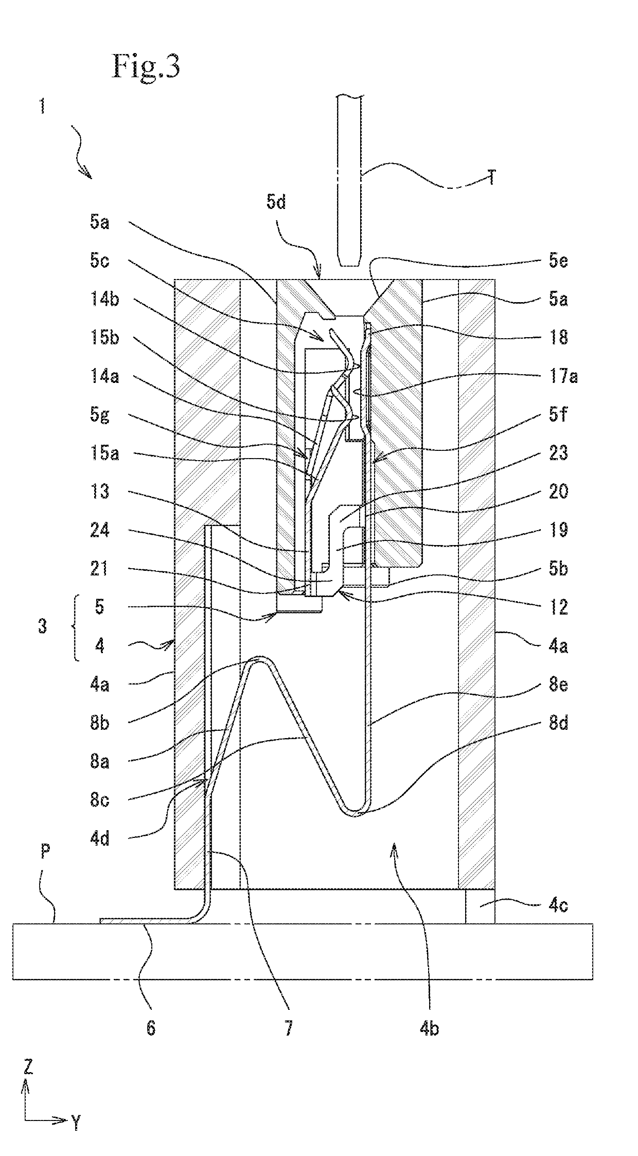
[0079]In the link portion 12 according to the present embodiment, one end of the elastic deformation portion 19 is connected to the first contact portion 10 via the first link arm portion 22 and the first bent portion 23, while the other end of the elastic deformation portion 19 is connected to the second contact portion 11 via the second link arm portion 25 and the second bent portion 24. In contrast, the link portion 12 may be formed into a Z-shape in such a manner that one end of a straight elastic deformation portion 19 is directly connected to the first contact portion 10 and the other end thereof is directly connected to the second contact portion 11.

[0080]In the present embodiment, as illustrated in FIG. 9, the elastic deformation portion 19 extends in the inserting direction Z. However, the elastic deformation portion 19 may be formed so as to extend obliquely with respect to the inserting direction Z. For example, the elastic deformation portion 19 may be disposed obliquely...


PUM


Abstract

In a connector, a terminal has a pair of contact portions that are fixed to a housing and disposed so as to provide a stable and reliable electrical connection. In the connector, a movable housing has a first contact portion fixation groove that supports a first contact portion of the terminal and a second contact portion fixation groove that supports a second contact portion. The terminal has a link portion that can join the first contact portion and the second contact portion to each other so as to be able to adjust the clearance therebetween. The link portion can absorb a variation in the clearance between the first contact portion fixation groove and the second contact portion fixation groove and a variation in the clearance between the first contact portion and the second contact portion.

Description

BACKGROUND OF INVENTION1. Field of the Invention[0001]The present invention relates to a connector that includes a terminal having a pair of contact portions that come into contact with a connection object and also includes a structure for retaining the contact portions in a housing.2. Description of the Related Art[0002]A known connector used for electronic devices is constituted by a terminal having a pair of contact portions that come into contact with a connection object and also includes a structure for retaining the contact portions in a housing (for example, Japanese Unexamined Patent Application Publication No. 2004-119050). Such a known connector includes the housing and the terminal. In the terminal, contact portions and a support base are formed. The contact portions nip the connection object so as to come into electrical contact therewith, and the support base supports the contact portions in an elastically displaceable manner. The contact portions have respective elasti...

Claims


Application Information

Patent Timeline
Patent Type & Authority Applications(United States)
IPC IPC(8): H01R13/11H01R12/91H01R13/502H01R12/71
CPCH01R13/112H01R12/91H01R13/502H01R12/716H01R13/115
Inventor SHIMBA, DAICHIOGURA, YOSHIYUKITANAKA, HITOSHI
Owner IRISO ELECTRONICS CO LTD
Why Eureka
Try Eureka