Simulated flame sheet and simulation candle

a flame sheet and simulation candle technology, applied in the field of decorative lighting, can solve the problems of affecting the overall appearance of the candle, great space for improvement, etc., and achieve the effects of improving the overall appearance, good candle simulation effect, and convenient assembly and disassembly

Active Publication Date: 2019-04-18
FOSHAN INNOVATION & QUALITY ELECTRONICS TECH CO LTD
View PDF1 Cites 2 Cited by
  • Summary
  • Abstract
  • Description
  • Claims
  • Application Information

AI Technical Summary

Benefits of technology

[0024]The flame-shaped chip of invention is easy to assemble and disassemble, and can protect the internal structure, so as to realize more vivid and realistic simulation of candles.
[0025]The invention of f

Problems solved by technology

This affects the overall appearance of the candle and is unfavorable to protect

Method used


Image

  • Simulated flame sheet and simulation candle
  • Simulated flame sheet and simulation candle
  • Simulated flame sheet and simulation candle

Examples


example 1

[0031]This example describes the invention when the needle serves as the fulcrum for swinging of the flame-shaped chip by way of lower support.

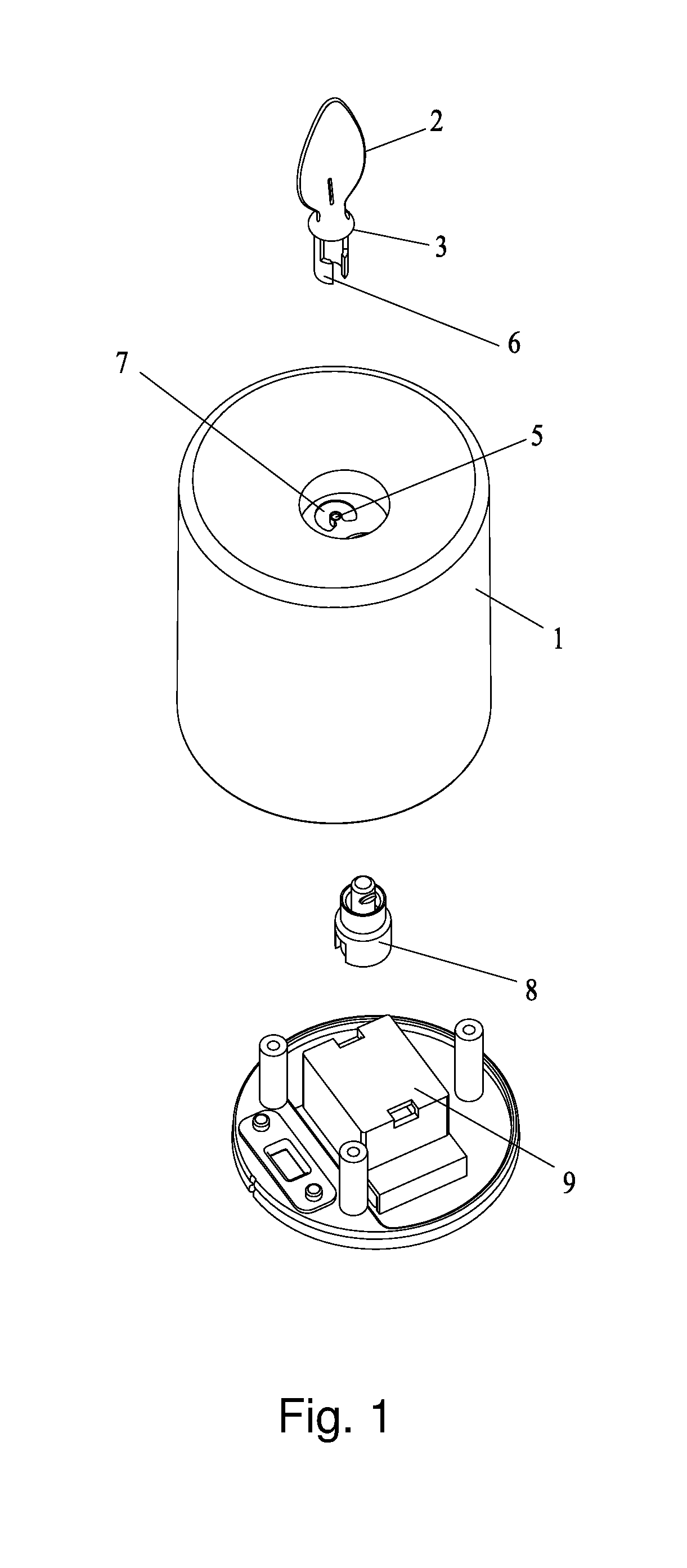
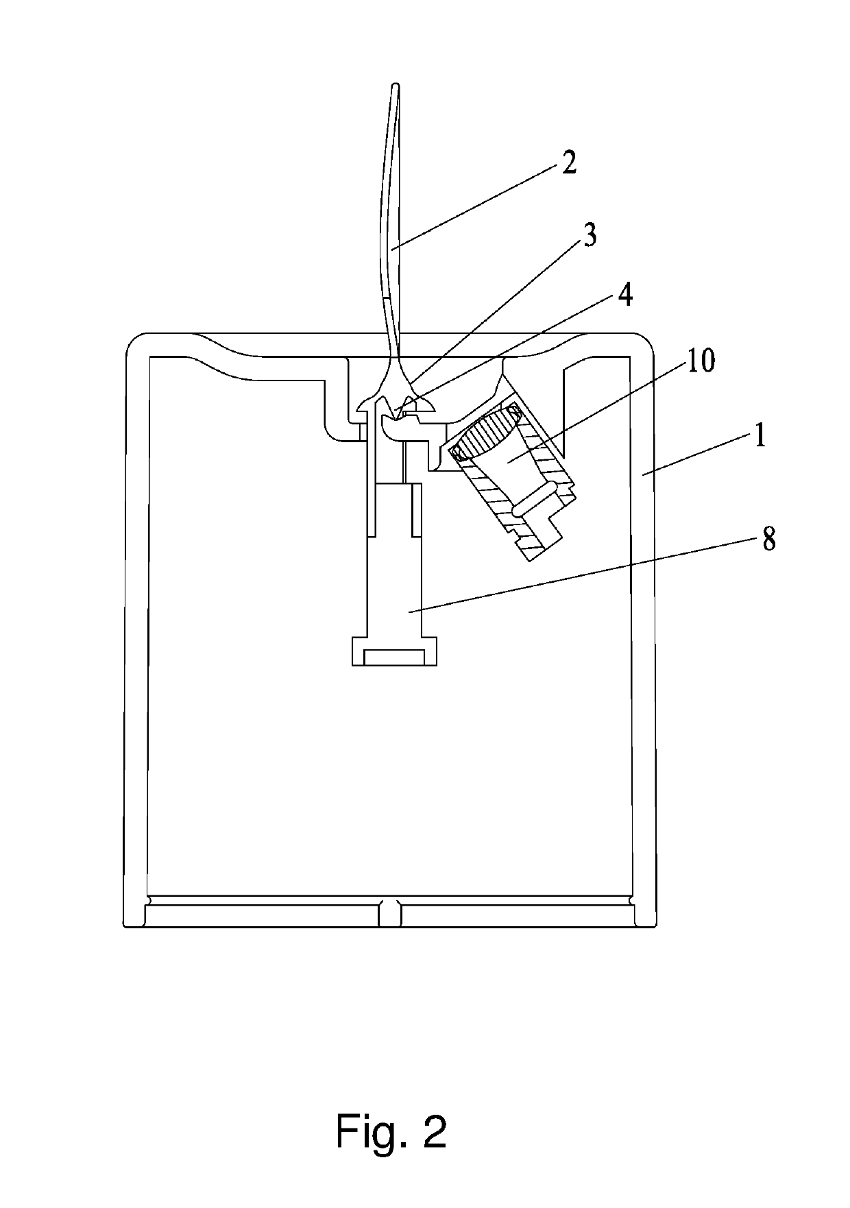
[0032]As shown in FIG. 1 and FIG. 2, the invention of flameless candle comprises of a flame-shaped chip and candle-shaped housing, wherein the flame-shaped chip includes an upper flame-shaped piece (2), an umbrella (3) and a needle (4). The umbrella (4) is arranged at the bottom of the upper flame-shaped piece (2) and used for covering, and the needle (4) is arranged in the umbrella (4) as the umbrella rod. The needle (4) and the umbrella (3) are integrally or separately arranged. The needle (4) is big end up or vice versa. The thinner end serves as the fulcrum for swinging of the flame-shaped chip by contacting with the top end face of the housing (1). The highest point of the needle (4) is higher than the lowest point of the top end face of the housing (1). The upper piece (2) and the umbrella (3) are combined with the housing (1) from the ...

example 2

[0038]This example describes the invention when the needle serves as the fulcrum for swinging of the flame-shaped chip by way of upper support.

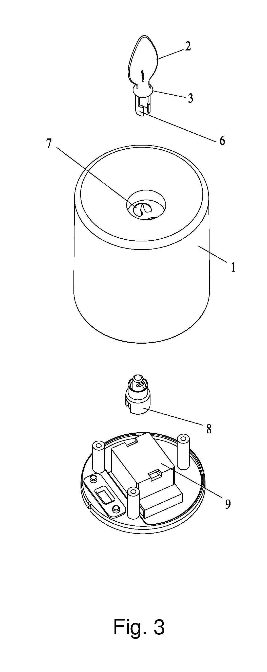
[0039]As shown in FIG. 3 and FIG. 4, the invention of flameless candle comprises of a flame-shaped chip and candle-shaped housing, wherein the flame-shaped chip includes an upper flame-shaped piece (2), an umbrella (3) and a needle (4). The umbrella (4) is arranged at the bottom of the upper flame-shaped piece (2) and used for covering, and the needle (4) is arranged in the umbrella (4) as the umbrella rod. The needle (4) and the umbrella (3) are separately arranged, and the needle (4) is arranged on the top end face of the housing (1). The needle (4) is thinner end up and the thinner end serves as the fulcrum for swinging of the flame-shaped chip. The highest point of the needle (4) is higher than the lowest point of the top end face of the housing (1). The upper piece (2) and the umbrella (3) are combined with the housing (1) from the upper...

example 3

[0045]The difference between this example and example 1 only lies in that: the structure of swinging mechanism is different.

[0046]The swinging mechanism may be structured in one of the following ways:

[0047](1) The driving device is a rotary disc, which is driven to horizontally rotate by a transmission shaft or a drive unit. The rotary disc is provided with a lever for triggering the driven device. The drive unit is arranged in the housing;

[0048](2) The driving device is a rotary column, which is driven to horizontally rotate by a transmission shaft or a drive unit and used for touching the driven device. The drive unit is arranged in the housing;

[0049](3) The driving device is a fan, and an air outlet of the fan is arranged at the bottom of the driven device;

[0050](4) The bottom of the driven device is provided with a magnet, and the driving device is a primary magnet device. The primary magnet device comprises a link piece, an upper magnet, a lower magnet, and an induction coil, w...


PUM


Abstract

The invention provides a flame-shaped chip, characterized by comprising an upper flame-shaped piece, an umbrella and a needle. The umbrella is arranged at the bottom of the upper flame-shaped piece and used for covering, and the needle is arranged in the umbrella as the umbrella rod. The needle and the umbrella are integrally or separately arranged. The flame-shaped chip is convenient to assemble and disassemble. The invention also provides a flameless candle, wherein the flameless candle comprises a flame-shaped chip and a candle-shaped housing. The flame-shaped chip comprises an upper flame-shaped piece, an umbrella and a needle. The umbrella is arranged at the bottom of the upper flame-shaped piece and used for covering, and the needle is arranged in the umbrella as the umbrella rod. The needle and the umbrella are integrally or separately arranged, and the needle is arranged on and/or contacts with the housing.

Description

FIELD OF THE INVENTION[0001]The invention relates to the decorative lighting technical field, or more specifically, a flame-shaped chip and flameless candle.BACKGROUND OF THE INVENTION[0002]The traditional candle is a kind of daily lighting tools. It is made of paraffin wax and can burn to give off light. Candles have important uses in birthday parties, religious festivals and other activities. At present, there is a kind of electronic flameless candle on the market, which simulates the light of candles through switch control, blow control, remote control and other control methods. This kind of electronic flameless candle is getting more and more popular on the market. It can be used in romantic, sentimental appeal, sweet, and happy times and festivals, meeting the special demands of festivals and household articles for people at all levels.[0003]When assembling the existing electronic flameless candle, first fix the flame-shaped chip inside the candle, and then wrap the candle-shap...

Claims


Application Information

Patent Timeline
IPC IPC(8): F21S10/04F21S6/00
CPCF21S10/046F21S6/001F21W2121/00F21S10/04
Inventor SHENG, GUANGRUN
Owner FOSHAN INNOVATION & QUALITY ELECTRONICS TECH CO LTD
Why Eureka
Try Eureka