
Three-dimensional scanner having pixel memory

a three-dimensional scanner and pixel memory technology, applied in measurement devices, instruments, electromagnetic wave reradiation, etc., can solve the problems of high dynamic range, high dynamic range, high dynamic range, and difficulty in determining the color reflectance characteristics of objects being measured in three dimensions

Active Publication Date: 2019-04-18
FARO TECH INC
View PDF0 Cites 11 Cited by
  • Summary
  • Abstract
  • Description
  • Claims
  • Application Information

AI Technical Summary

Benefits of technology

The present invention is a triangulation scanner system that includes a projector, a first camera, and a processor. The system uses patterned light to determine the 3D coordinates of points on an object. The first camera captures images of the object during two time intervals, and the processor analyzes the images and the relative position of the projector and camera to determine the 3D coordinates of the object. The system can also include an analog-to-digital converter to convert signals from the camera to digital signals. The technical effect of the invention is to provide a more accurate and efficient method for determining the 3D coordinates of points on an object.

Problems solved by technology

Another difficulty encountered by triangulation scanners the ability to acquire dense detail from 2D camera images while still retaining relatively high 3D accuracy using triangulation methods.
Another difficulty of triangulation scanners is obtaining high-dynamic-range 3D images and colored 3D images based on two-dimensional (2D) color images having high dynamic range.
Another difficulty of triangulation scanners is removing ambiguities in determining 3D coordinates A further difficulty is in determining color reflectance characteristics of objects being measured in three dimensions.

Method used


Image

  • Three-dimensional scanner having pixel memory
  • Three-dimensional scanner having pixel memory
  • Three-dimensional scanner having pixel memory

Examples


Embodiment Construction

[0077]Embodiments of the present invention provide advantages to triangulation scanners by avoiding saturation of camera arrays by bright background light such as sunlight. Further embodiments provide advantages in capturing high object detail based on 2D camera images while retaining relatively high 3D accuracy using triangulation scan data. Further embodiments provide advantages in obtaining high-dynamic-range 3D images and colored 3D images based on 2D color images having high dynamic range. Further embodiments provide advantages to triangulation scanners by removing ambiguities in determining 3D coordinates. Further embodiments provide multi-spectral capability for determining color reflectance characteristics of objects being measured in three dimensions.

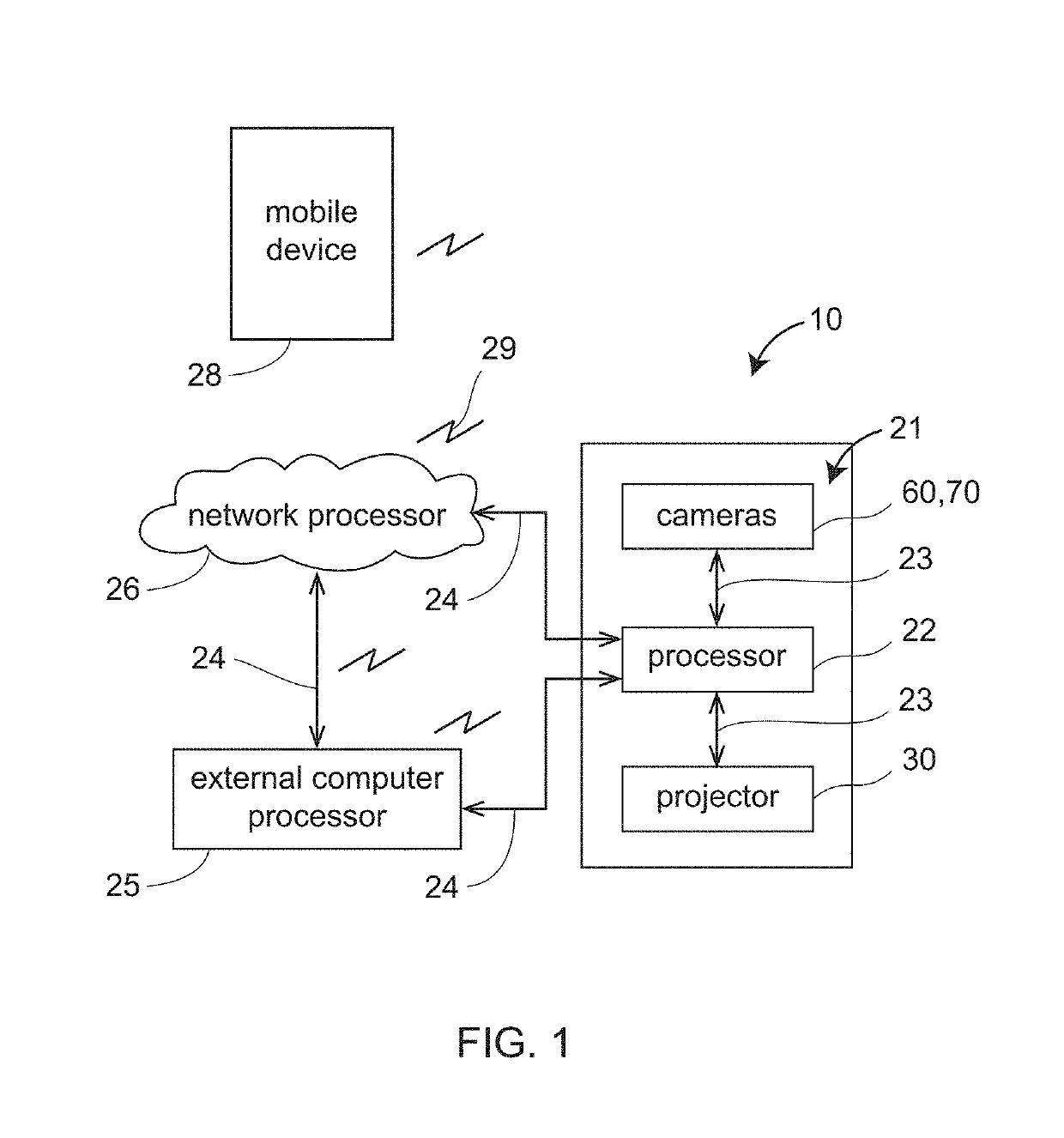
[0078]In an embodiment illustrated in FIG. 1, the 3D imager 10 includes an internal electrical system 21 having a processor 22 that communicates with electrical components of projector 30 and cameras 60, 70 by electrical lines ...


PUM


Abstract

A triangulation scanner includes a projector, a camera, and a processor, the projector projecting a first pattern of light on a first point during first intervals and a no light during second intervals, the camera including an optical detector, a first accumulator, and a second accumulator, the optical detector receiving reflected light from the first point, the first and second accumulators summing signals from the optical detector during the first and second intervals, respectively, the processor determining 3D coordinates of the first point based at least in part on the first pattern, the summed signals from the first and second accumulators, and a speed of light in air.

Description

CROSS REFERENCE TO RELATED APPLICATIONS[0001]This application claims the benefit of U.S. Provisional Application Ser. No. 62 / 572,002, filed Oct. 13, 2017, the entire disclosure of which is incorporated herein by reference.FIELD OF THE INVENTION[0002]The subject matter disclosed herein relates in general to a three-dimensional (3D) measuring device that uses reflected light to measure 3D coordinates of objects.BACKGROUND[0003]One type of 3D measuring device is a triangulation scanner that uses a triangulation method to measure the 3D coordinates of points on an object. The triangulation scanner usually includes a projector that projects onto a surface of the object either a pattern of light in a line or a pattern of light covering an area. A camera is coupled to the projector in a fixed relationship, for example, by attaching a camera and the projector to a common frame. The light emitted from the projector is reflected off the object surface and is detected by the camera. Since the ...

Claims


Application Information

Patent Timeline
Patent Type & Authority Applications(United States)
IPC IPC(8): G01B11/25G01S17/89G01S17/894H04N23/90
CPCG01B11/25G01B11/2545G01S17/894H04N23/90G01S17/89
Inventor WOLKE, MATTHIASHEIDEMANN, ROLFHILLEBRAND, GERRITDORING, DANIEL
Owner FARO TECH INC
Learn More