Relay device
a relay device and relay technology, applied in relays, emergency power supply arrangements, transportation and packaging, etc., can solve the problems of inability to effectively measure and lack of function, and achieve the effect of accurately detecting and distinguishing
- Summary
- Abstract
- Description
- Claims
- Application Information
AI Technical Summary
Benefits of technology
Problems solved by technology
Method used
Image
Examples
embodiment 1
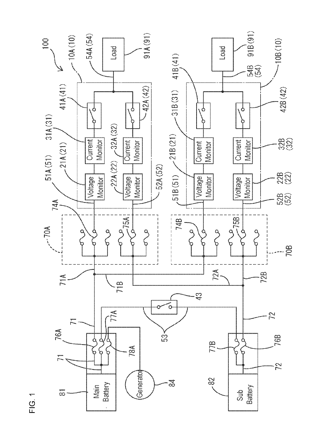
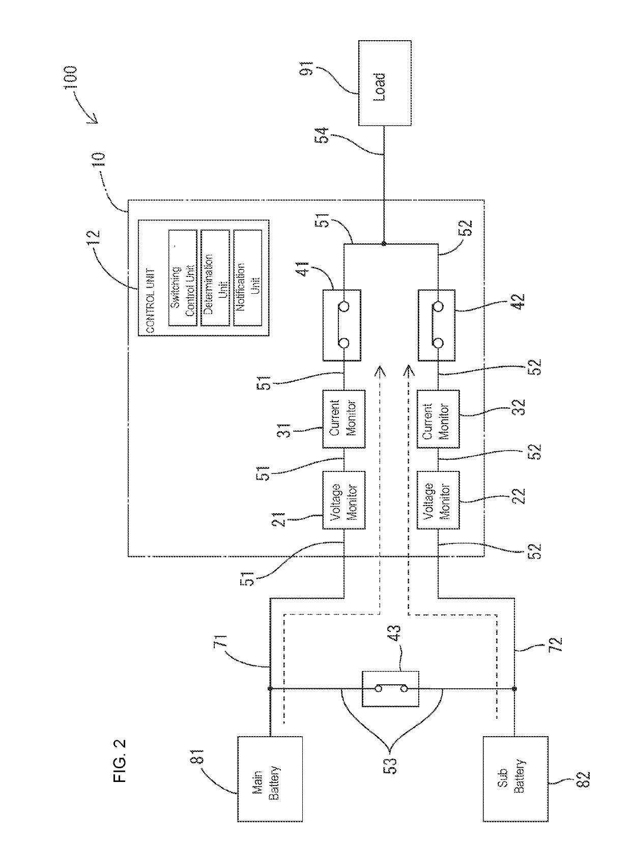
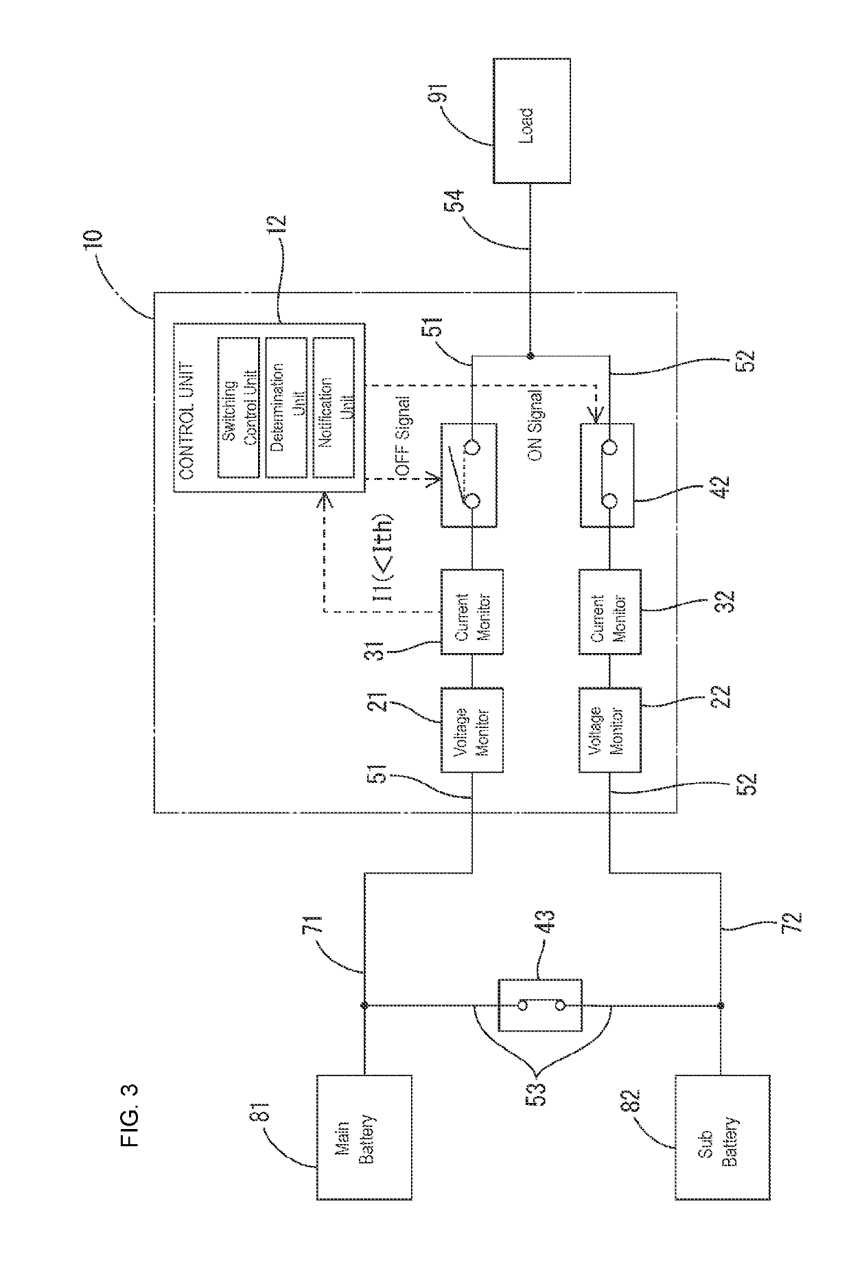
[0036]The following will describe Embodiment 1 in which the present description is embodied. An in-vehicle power supply system 100 (hereinafter, also referred to as “system 100”) is configured as a power supply system for a vehicle that includes a plurality of batteries (a first power storage unit 81 and a second power storage unit 82). A relay device 10 constitutes a portion of the in-vehicle power supply system 100. Note that the in-vehicle power supply system 100 in FIG. 1 includes two relay devices 10 (a first relay device 10A and a second relay device 10B) that have the same function.
[0037]The first power storage unit 81 functions as a main power supply, and consists of, for example, a well-known battery such as a lead battery. In the following description and the drawings, the first power storage unit 81 is also referred to as “main battery”. A terminal on a high-potential side of the first power storage unit 81 is electrically connected to a wiring portion 71 provided outside...
embodiment 2
[0084]Next, Embodiment 2 will be described with reference to FIG. 7 and so on.
In Embodiment 1, an example was described in which the entire relay device 10 is configured as an integrated unit device. In contrast, a relay device relay device 210 of Embodiment 2 shown in FIG. 7 differs from the relay device 10 of Embodiment 1 only in that it is configured with a plurality of unit devices, a control unit is provided in each of the unit devices, and a communication line 214 connecting among the unit devices is provided. Accordingly, in the relay device 210 of Embodiment 2, structures that are the same as those of the relay device 10 of Embodiment 1 are given the same reference numerals of each portion of the relay device 10, and their detailed descriptions are omitted.
[0085]In the example shown in FIG. 7, the first relay unit 41, the first voltage detection unit 21, the first current detection unit 31, and a control unit 212A are mounted, for example, on the same board, constituting a u...
embodiment 3
[0088]Next, Embodiment 3 will be described with reference to FIG. 8 and so on. A relay device 310 of Embodiment 3 has a more specific configuration of the relay device 10 of Embodiment 1, includes all of the structures and functions of the aforementioned relay device 10 of Embodiment 1, and has a configuration in which further structures and functions are added. Accordingly, the same portions of Embodiment 1 in FIGS. 8 and 9 are given the same reference numerals in FIGS. 1 and 2, and the detailed description of them is omitted. Specifically, the in-vehicle power supply system 300 shown in FIG. 8 differs from the in-vehicle power supply system 100 shown in FIG. 1 only in that a third power storage unit 316 is added. The relay device 310 of Embodiment 3 shown in FIG. 9 and so on differs from the relay device 10 of Embodiment 1 shown in FIG. 2 and so on in that the third power storage unit 316 is added, and other portions are the same as those of the relay device 10 of Embodiment 1.
[00...
PUM
 Abstract
Description
Claims
Application Information
 - R&D
- Intellectual Property
- Life Sciences
- Materials
- Tech Scout
- Unparalleled Data Quality
- Higher Quality Content
- 60% Fewer Hallucinations
Browse by: Latest US Patents, China's latest patents, Technical Efficacy Thesaurus, Application Domain, Technology Topic, Popular Technical Reports.
© 2025 PatSnap. All rights reserved.Legal|Privacy policy|Modern Slavery Act Transparency Statement|Sitemap|About US| Contact US: help@patsnap.com


