
Vehicle control apparatus

a technology of control apparatus and control device, which is applied in the direction of motor/generator/converter stopper, dynamo-electric converter control, stopping arrangement, etc., can solve the problems of sudden decrease of the rotation (or completely zero), and the output torque of the electric motor becomes zero, so as to achieve more accurate

Inactive Publication Date: 2016-09-15
TOYOTA JIDOSHA KK
View PDF4 Cites 2 Cited by
  • Summary
  • Abstract
  • Description
  • Claims
  • Application Information

AI Technical Summary

Benefits of technology

The present invention provides a vehicle control apparatus that can accurately determine whether or not the vehicle is stopped based on the number of revolutions of the three-phase AC motor and the presence or absence of the stop operation. Compared to a control apparatus that only determines the vehicle is stopped if the number of revolutions of the internal combustion engine is less than or equal to a predetermined threshold value, the present invention has higher accuracy in detecting the number of revolutions of the three-phase AC motor. Additionally, the present invention provides a mechanism for controlling the vehicle to prevent the occurrence of the sense of torque falling without reducing drivability, by performing the three-phase short-circuit control after a lapse of the predetermined period from the particular control command. This ensures that the command torque of the lower controlling device can be brought close to zero, which avoids a situation in which the three-phase short-circuit control cannot be performed.

Problems solved by technology

By the way, if the three-phase short-circuit control is performed, sufficient torque to be a braking force in the electric motor is generated in a high vehicle speed region (i.e. in a region in which the number of revolutions of the electric motor is high); however, the electric motor cannot rotate in a low vehicle speed region or during the stop of a vehicle (i.e. in a region in which the number of revolutions of the electric motor is extremely low or zero), resulting in nearly zero (or completely zero) rotation, and the output torque of the electric motor becomes zero.
Thus, for example, if the three-phase short-circuit control is performed immediately before the vehicle stops in a case where the torque of the electric motor is not zero, then, the torque of the electric motor suddenly decreases, and that gives a driver of the vehicle a sense of torque falling, which is technically problematic.

Method used


Image

  • Vehicle control apparatus
  • Vehicle control apparatus
  • Vehicle control apparatus

Examples


first embodiment

(1) First Embodiment

[0041]Firstly, with reference to FIG. 1 to FIG. 5, a first embodiment will be explained.

(1-1) Configuration of Vehicle in First Embodiment

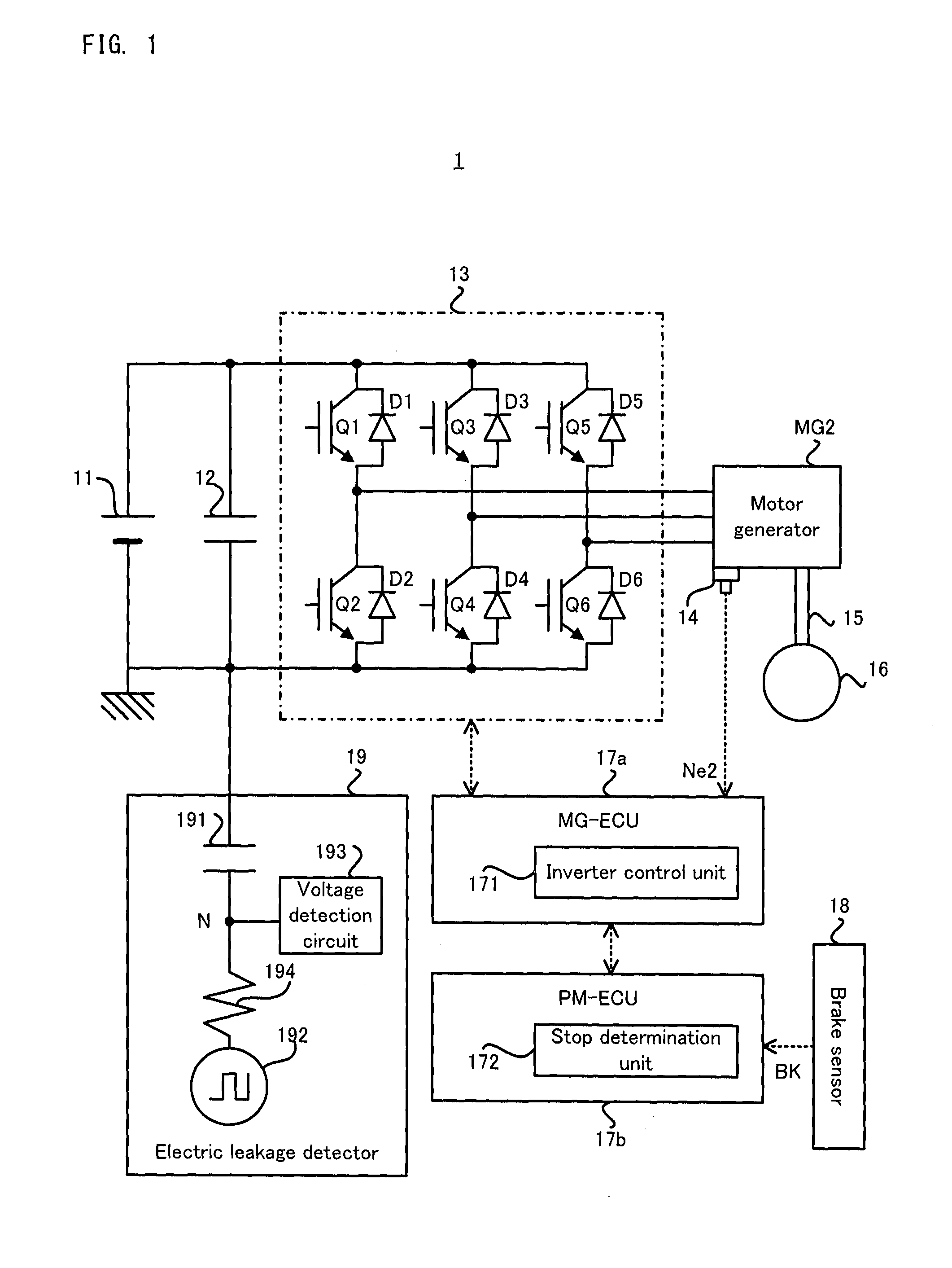
[0042]Firstly, with reference to FIG. 1, a configuration of a vehicle 1 in the first embodiment will be explained. FIG. 1 is a block diagram illustrating a configuration of a vehicle in a first embodiment.

[0043]As illustrated in FIG. 1, the vehicle 1 is provided with a direct current (DC) power supply 11, a smoothing capacitor 12, an inverter 13 which is one specific example of the “power converter”, a motor generator MG2 which is one specific example of the “three-phase alternating current (AC) motor”, a rotation angle sensor 14, a drive shaft 15, a driving wheel 16, a MG-ECU 17a which is one specific example of the “lower controlling device”, and a PM-ECU 17b which is one specific example of the “upper controlling device”, and a brake sensor 18 and an electric leakage detector 19.

[0044]The DC power supply 11 is a chargeable p...

second embodiment

(2) Second Embodiment

[0115]Next, a second embodiment will be explained with reference to FIG. 6 and FIG. 7. In the second embodiment, the operation is partially different from that of the first embodiment described above, and the other part is substantially the same. Thus, hereinafter, the different part from the first embodiment will be explained in detail, and the explanation of the duplicate part will be omitted as occasion demands.

[0116]Firstly, with reference to FIG. 6, a flow of the stop determination operation performed in the vehicle 1 in the second embodiment and accompanying three-phase short-circuit control will be explained. FIG. 6 is a flowchart illustrating the flow of the stop determination operation in the second embodiment.

[0117]As illustrated in FIG. 6, if the stop determination operation is started in the vehicle 1 in the second embodiment, the stop determination unit 172 performs each process, in order, from a step S200 to a step S204 which are the same as the st...

third embodiment

(3) Third Embodiment

[0124]Next, a third embodiment will be explained with reference to FIG. 8 and FIG. 9. In the third embodiment, the operation is partially different from those of the first and second embodiments described above, and the other part is substantially the same. Thus, hereinafter, the different part from the first and second embodiments will be explained in detail, and the explanation of the duplicate part will be omitted as occasion demands.

[0125]In the third embodiment, the MG-ECU 17a is configured to perform addition control of the torque independently of the PM-ECU 17b. Hereinafter, the addition control will be specifically explained, and its possible problem will be explained by using a second comparative example illustrated in FIG. 8. FIG. 8 is a chart illustrating a change in the torque command value when a vehicle in a second comparative example stops. FIG. 8 illustrates as if the HV torque command and the MG torque command when the vehicle stops linearly decr...


PUM


Abstract

A vehicle control apparatus is provided with an upper controlling device and a lower controlling device. The upper controlling device has: a first determining device configured to determine whether or not the number of revolutions of a three-phase AC motor is less than or equal to a predetermined threshold value and whether or not a stop operation which can stop the vehicle is performed; a second determining device configured to determine that the vehicle is stopped if it is determined that the number of revolutions of the three-phase AC motor is less than or equal to the predetermined threshold value and that the stop operation is performed; and a commanding device configured to output a particular control command for setting the state of a power converter to a particular state if it is determined that the vehicle is stopped. The lower controlling device controls the power converter to be in the particular state after a lapse of a predetermined period from the reception of the particular control command.

Description

TECHNICAL FIELD[0001]The present invention relates to, for example, a vehicle control apparatus configured to control a vehicle provided with an electric motor.BACKGROUND ART[0002]Recently, the vehicle provided with the electric motor (or a so-called motor) has been attracting attention. As an example of the vehicle provided with the electric motor as described above, there is known a hybrid vehicle provided with both the electric motor and an internal combustion engine (e.g. refer to Patent document 1).[0003]The Patent document 1 discloses a technology in which three-phase short-circuit control of the electric motor is performed to stop the rotation of the internal combustion engine at an early stage if the number of revolutions of the internal combustion engine is less than the predetermined number of revolutions in the hybrid vehicle as described above.PRIOR ART DOCUMENTSPatent Documents[0004]Patent document 1: Japanese Patent Application Laid Open No. 2006-288051SUMMARY OF THE I...

Claims


Application Information

Patent Timeline
Patent Type & Authority Applications(United States)
IPC IPC(8): B60L7/00H02P3/22H02P27/08B60L15/20
CPCB60L7/003H02P27/08H02P3/22B60L15/2009B60L3/0069B60L3/12B60L2260/12B60L2260/20H02P3/025H02P6/24Y02T10/64Y02T10/72
Inventor TSUJII, SHINTARONIIMI, YOSHITAKAOKAMURA, MASAKIANG, WANLENGYAGUCHI, HIDEAKIMORISAKI, KEISUKEOYOBE, HICHIROSAI
Owner TOYOTA JIDOSHA KK
Learn More