
Plate-shaped flower carrier

a plate-shaped, flower-carrying technology, applied in the direction of containers, tray containers, packaged goods, etc., can solve the problems of limiting the speed with which carriers can be filled with flowers, and not being suited for mechanical introduction of flower stems

Inactive Publication Date: 2002-02-07
UNIRES PARTICIPATIES +1
View PDF0 Cites 13 Cited by
  • Summary
  • Abstract
  • Description
  • Claims
  • Application Information

AI Technical Summary

Benefits of technology

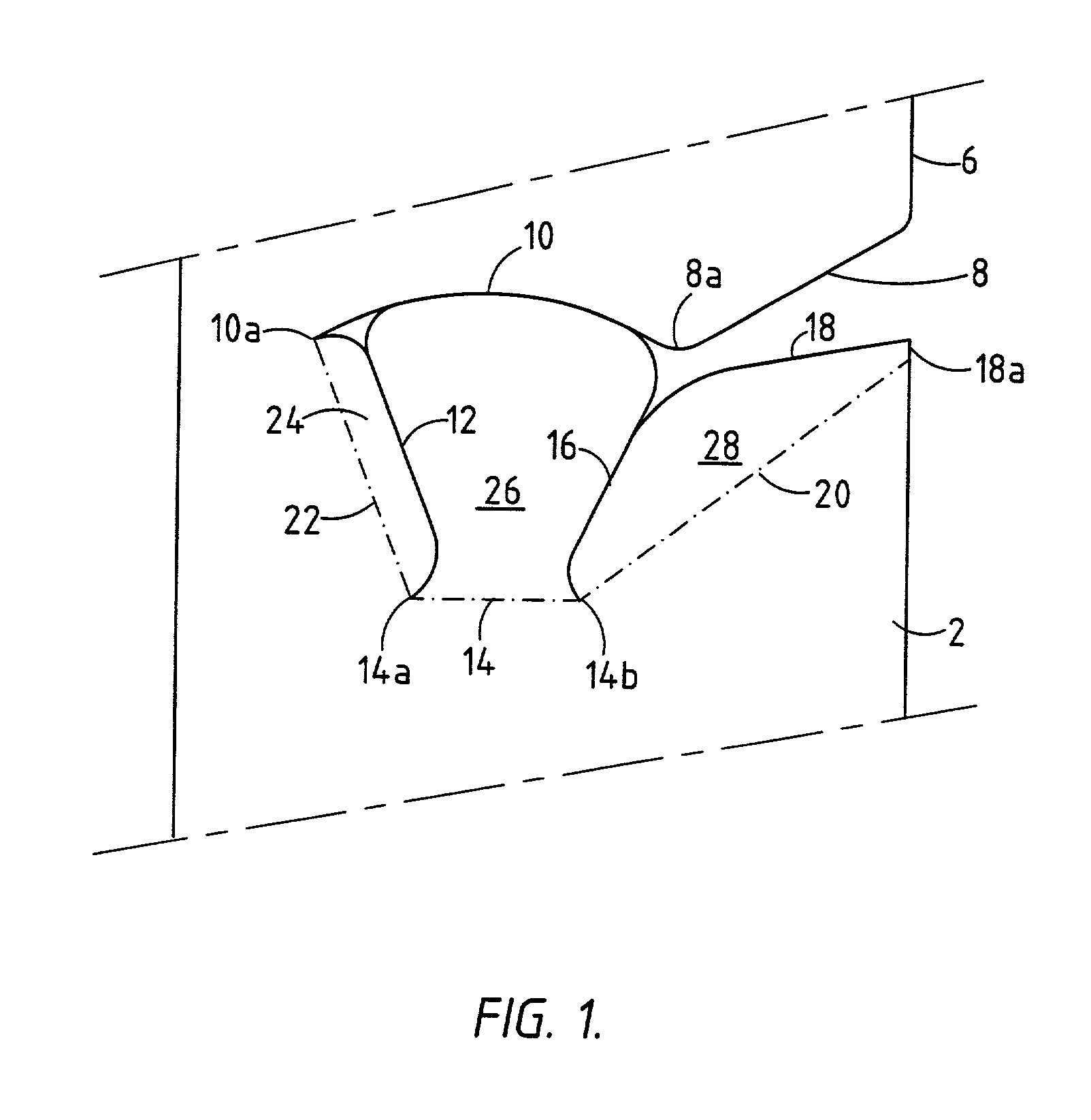
[0006] By this simple measure, which in no way increases the cost of the carriers, is obtained that it is not necessary anymore to introduce the flowers with the end of the stem thereof aimed at an opening, but must be slided from the side into the infeed channel. Practice has shown that this sliding motion can be effected much faster, much more accurate and with less manual action and less chance of damage than is possible with the way of insertion as done with the prior art. A mechanical infeed of the stems is simply possible as these stems must only be guided along the side of the carrier to the neighbourhood of an infeed slot.
[0008] In a preferred embodiment the stem supporting edge is formed by the folding edge of a stem supporting lip, cut out from the carried material and folded over to the backside of the carrier. With this measure it is obtained that the transition between flower head and stem is supported by a soft (folding) edge, having double the thickness of the carrier material while the supporting lip, which is folded over to the backside, engages resiliently the stem and prevents that an abrupt buckle is formed in the stem at the position of the transition to the flower head.
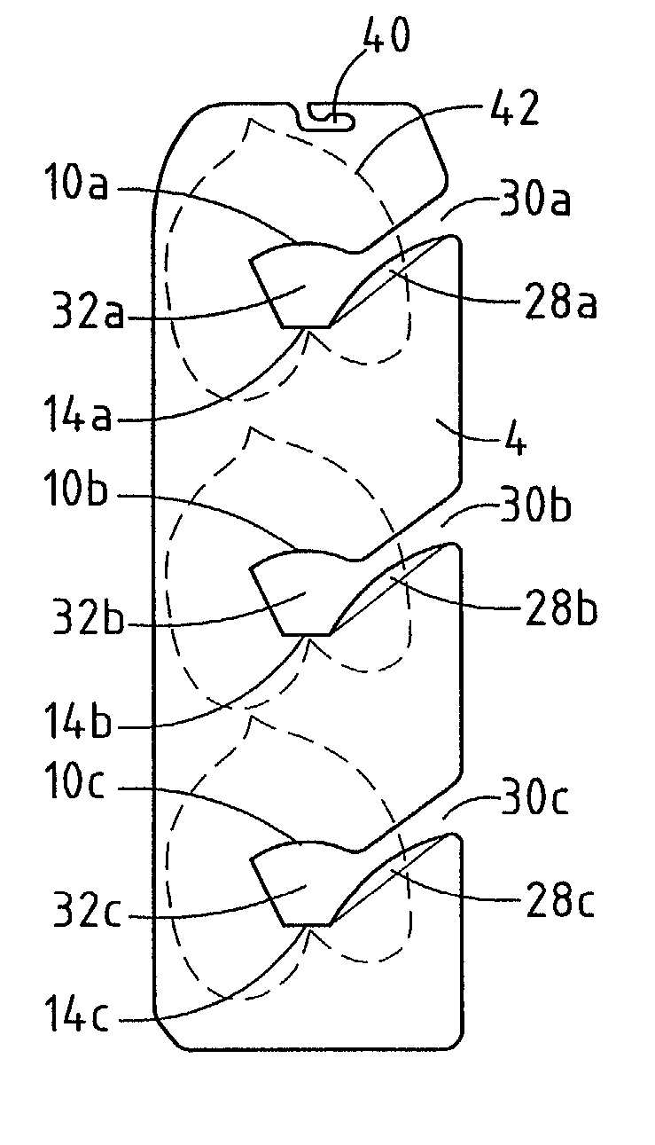
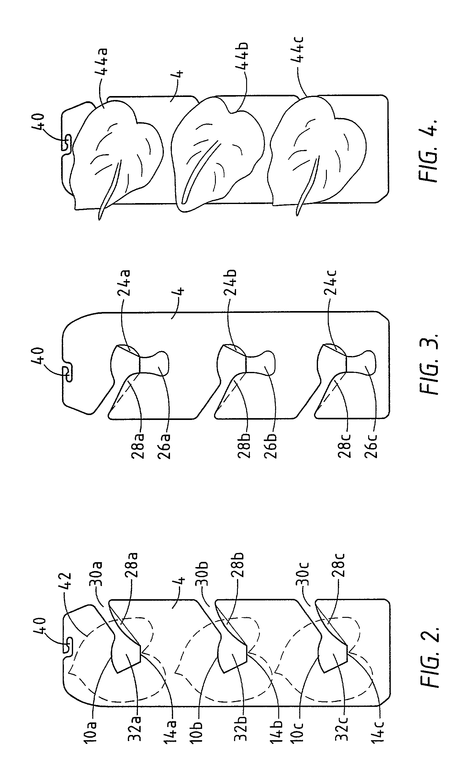
[0010] When around each opening the contours of a flower to be supported therein are shown, sorting of the flowers during the packing as to their size is made easier. Of course the carrier can also carry other relevant information.

Problems solved by technology

All known plate-shaped carriers of this kind have the drawback that the respective flower stems, must be introduced therein via the infeed openings, which have an edge closed into itself.
This is in itself a simple operation but, when this handling must be repeated a great number of times such as necessary for packing many flowers it is felt as being a nuisance and cumbersome, can result into RSI-complaints, and limits the speed with which carriers can be filled with flowers.
Furthermore such a configuration is not suited for a mechanical introduction of the flower stems.

Method used


Image

  • Plate-shaped flower carrier
  • Plate-shaped flower carrier
  • Plate-shaped flower carrier

Examples


Embodiment Construction

[0021] FIG. 1 shows a front view of part of a sheet 2, provided with incisions and folding edges from which is made the carrier to be described hereinafter; in fact the part in FIG. 1, which is denoted with reference numeral 2, is a part of a carrier which is denoted with reference numeral 4 in the other drawings. The sheet is preferably made up from thin corrugated cardboard which can easily be folded and then has a soft surface at the folding edge. From the right hand side 6 a first incision 8 runs downwardly which at its end 8a merges into a convex incision 10. From the left hand end 10a thereof an incision 12 runs under an acute angle with the longitudinal axis of the sheet 2 to the left edge 14a of a folding line 14, and from the right hand edge 14b thereof a second incision 16 starts, extending to the incision 10. This incision 16 merges into the incision 18 which runs to the right hand edge 6 and ends at a distance below the start of the incision 8. The meeting point 18a betw...


PUM


Abstract

The invention relates to a plate-shaped carrier for flowers, having in its plane a number of accommodating openings for the respective flower stems, comprising, for easing the insertion of the respective flower stems in an accommodating opening, a flower stem infeed slot, starting from a longitudinal edge of the carrier and running downwardly under an acute angle with this edge into the accommodating opening.

Description

[0001] The invention relates to a plate-shaped flower carrier with in the plane thereof a number of accommodating openings for accommodating the respective flower stems.DESCRIPTION OF THE PRIOR ART[0002] Such plate-shaped carriers are known from practice. A particular embodiment thereof, in which a number of such carriers abut each other and are combined to an in cross-section polygonal sleeve is subject of the Dutch patent specification 1002176, while another embodiment thereof, particularly destined to be housed in a special packing box, is described in the U.S. Pat. No. 5,217,117. Still another embodiment of such an elongate carrier is subject of the European patent application 0.395.827 A1 and this embodiment is destined to be combined with a special outer case.[0003] All known plate-shaped carriers of this kind have the drawback that the respective flower stems, must be introduced therein via the infeed openings, which have an edge closed into itself. This is in itself a simple...

Claims


Application Information

Patent Timeline
IPC IPC(8): B65D5/50B65D73/00B65D85/50
CPCB65D5/5035B65D5/5059B65D73/0042B65D85/505
Inventor VAN DER STOEP, CORNELIS J.BRAXHOOFDEN-VAN DER HEIDE, IRIS C.KLEIMAN, CASPERVERBRUGGE, JEROEN K.STRUIJK, JACOB
Owner UNIRES PARTICIPATIES
Learn More