Optical element, optical system, and image pickup apparatus
- Summary
- Abstract
- Description
- Claims
- Application Information
AI Technical Summary
Benefits of technology
Problems solved by technology
Method used
Image
Examples
example 1
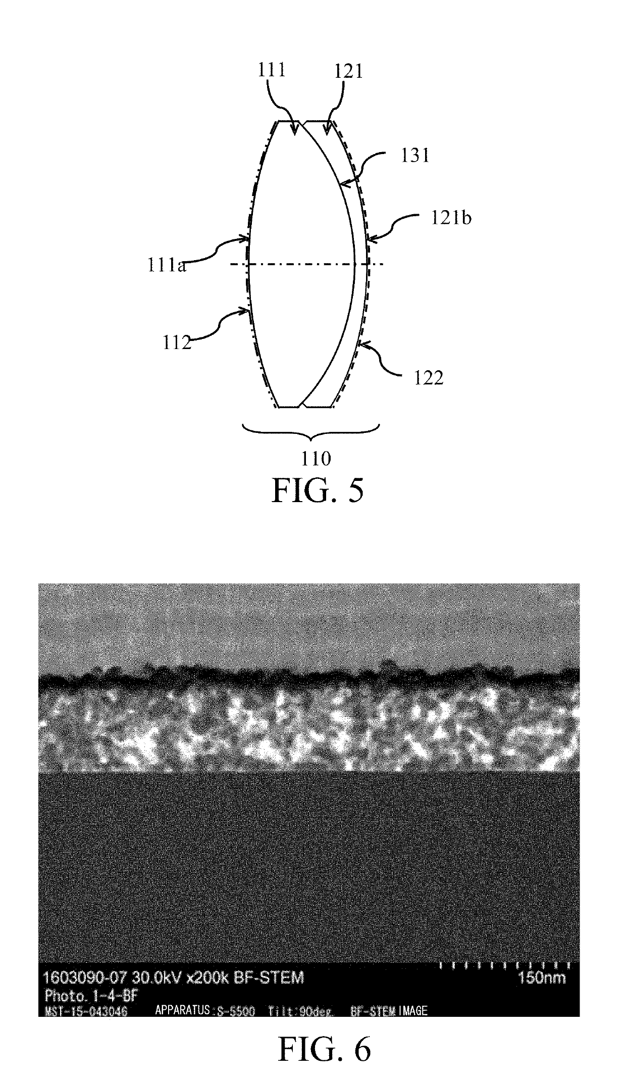
[0042]FIG. 5 is a sectional view of a cemented lens 110 according to this example. The cemented lens 110 is an optical element made by adhering a biconvex lens 111 and a concave meniscus lens 121 to each other by the adhesive on the cemented surface 131. The biconvex lens 111 is made of OHARA Corp. S-FPL51 with a refractive index nd of 1.497 for the d-line (wavelength of 587.56 nm). The concave meniscus lens 121 is made of OHARA Corp. S-LAH65V with a refractive index nd of 1.804 for the d-line. The cemented surface 131 has an outer diameter of 30.0 mm. This embodiment forms an ordinary antireflection film 112 comprised of a dielectric multilayer film on a light incident surface 111a of the cemented lens 110, and an antireflection film 122 according to the present invention on a light exit surface 121b of the cemented lens 110. Table 1 shows designed values of the antireflection film 122.
[0043]A description will now be given of an illustrative manufacturing method of the cemented len...
example 2
[0063]FIG. 8 is a sectional view of a cemented lens 210 according to this example. The cemented lens 210 is an optical element made by adhering a biconvex lens 211 and a biconcave lens 212 to each other by the adhesive on a cemented surface 231. The biconvex lens 211 is made of HOYA Corp. TAFD 30 with a refractive index nd of 1.883 for the d-line. The biconcave lens 212 is made of OHARA Corp. S-TIM8 with a refractive index dn of 1.596 for the d-line. The cemented surface 231 has an outer diameter of 42.8 mm. This embodiment forms an ordinary antireflection film 212 composed of a dielectric multilayer film on a light incident surface 211a of the cemented lens 210, and the antireflection film 222 according to the present invention on a light exit surface 221b of the cemented lens 210. Table 2 shows designed values of the antireflection film 222. The antireflection film 222 includes a base layer formed by a vacuum deposition method, and a low refractive index layer formed on the base l...
example 3
[0068]FIG. 10 is a sectional view of a cemented lens 310 according to this example. The cemented lens 310 is an optical element made by adhering a concave meniscus lens 311 and a convex meniscus lens 312 to each other by the adhesive on a cemented surface 331. The concave meniscus lens 311 is made of OHARA Corp., S-LAH60 with a refractive index nd of 1.834 for the d-line. The convex meniscus lens 312 is made of OHARA Corp., S-FPL53 with a refractive index nd of 1.439 for the d-line. The cemented surface 331 has an outer diameter of 84.0 mm. This embodiment forms an ordinary antireflection film 312 composed of a dielectric multilayer film on a light incident surface 311a of the cemented lens 310, and the antireflection film 322 according to the present invention on a light exit surface 321b of the cemented lens 310. Table 3 shows designed values of the antireflection film 322. The antireflection film 322 includes a base layer formed by a vacuum deposition method, and a low refractive...
PUM
| Property | Measurement | Unit |
|---|---|---|
| Density | aaaaa | aaaaa |
| Density | aaaaa | aaaaa |
| Nanoscale particle size | aaaaa | aaaaa |
Abstract
Description
Claims
Application Information
 - R&D
- Intellectual Property
- Life Sciences
- Materials
- Tech Scout
- Unparalleled Data Quality
- Higher Quality Content
- 60% Fewer Hallucinations
Browse by: Latest US Patents, China's latest patents, Technical Efficacy Thesaurus, Application Domain, Technology Topic, Popular Technical Reports.
© 2025 PatSnap. All rights reserved.Legal|Privacy policy|Modern Slavery Act Transparency Statement|Sitemap|About US| Contact US: help@patsnap.com


