
Device using a virtually-imaged phased array (VIPA) with an improved transmission wave characteristic of output light

a technology of output light and phased array, which is applied in the field of devices using a virtually-imaged phased array to generate wavelength dispersion, can solve the problems of distortion, degrade the quality of signals in the system, and the time width of signal optical pulses is broadened in the optical fiber, so as to suppress the degradation of optical signals and level the transmission wavelength characteristic of vipa

Inactive Publication Date: 2007-04-03
FUJITSU LTD
View PDF15 Cites 2 Cited by
  • Summary
  • Abstract
  • Description
  • Claims
  • Application Information

AI Technical Summary

Benefits of technology

[0038]It is an object of the present invention to provide means for suppressing optical loss and improving the wavelength characteristic of output light in an economical way in a device using a VIPA in order to compensate for wavelength dispersion.
[0040]According to the present invention, the transmission wavelength characteristic of a VIPA can be leveled easily and in an economical way, and an fiber optic communication system suppressing the degradation of optical signals passing through the transmission band of the VIPA and transmitting high-quality optical signals can be realized accordingly.

Problems solved by technology

However, wavelength dispersion, which is also called “chromatic dispersion”, degrades the quality of the signals in the system.
Therefore, the time width of the signal optical pulse is broadened in the optical fiber and distortion occurs.
However, the production of a dispersion compensation fiber is expensive and a fairly long fiber is needed to sufficiently compensate for the wavelength dispersion generated in the transmission line fiber.
Therefore, optical loss increases and also dimensions become large, which are problems.
Therefore, a wavelength band sufficient to compensate for light containing many wavelengths such as wavelength division multiplexed light cannot be obtained.
In this case, the system costs dearly.
However, an actual spatial grating pair array cannot apply dispersion sufficient to compensate for a fairly large amount of chromatic dispersion generated in an fiber optic communication system.
Therefore, such a spatial grating pair array is not practical.
However, the transmittance characteristic by wavelength of a device using a VIPA to compensate for wavelength dispersion is not flat and is of round-top shape with a round peak around the center frequency of each transmission band, as shown in FIG. 5, which is another problem.
If there is a device with such a transmission characteristic in an optical transmission line, a signal optical pulse waveform transmitted from a transmitter is distorted and a signal cannot be accurately transmitted.
In particular, if in a long-haul fiber optic communication system requiring the compensation of large wavelength dispersion, wavelength dispersion is compensated for by multi-connecting many devices using a VIPA, the undesirable transmission characteristics are overlapped and a signal optical pulse greatly degrades.
However, a plurality of light rays multiply reflected in the VIPA interfere with one another and the wavelength of light, the strength of which is increased and output, varies for each plane wave component with a different travel direction.
Secondly, since light with each wavelength output from a VIPA has a plurality of possible travel directions each with a different order of interference, the strength of the light is distributed among the plurality of pieces of light each with a different order of interference.
Therefore, when light with an unnecessary order of interference to be discarded is output from the VIPA, there is optical loss corresponding to the unnecessary order of interference.
However, the transmission characteristic of a device using a VIPA sometimes has an asymmetrical shape with a peak wavelength as a center in which a wavelength width on a short wavelength side and a wavelength width on a long wavelength side are different in designing, as shown in FIG. 7, and it cannot be leveled in a strict sense.
However, the grater the number of filters, the greater the loss of transmitted light and the higher the cost of the system, which is not practical.

Method used


Image

  • Device using a virtually-imaged phased array (VIPA) with an improved transmission wave characteristic of output light
  • Device using a virtually-imaged phased array (VIPA) with an improved transmission wave characteristic of output light
  • Device using a virtually-imaged phased array (VIPA) with an improved transmission wave characteristic of output light

Examples


Embodiment Construction

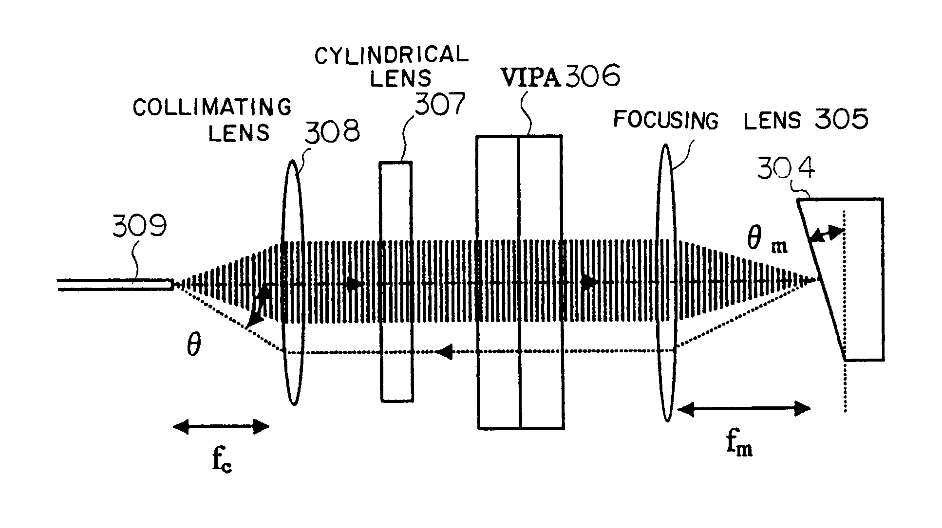
[0077]Embodiments of the present invention provide a device comprising a mirror in a shape so as to generate almost uniform wavelength dispersion in an angular dispersion direction generated by a VIPA regardless of each wavelength output by the VIPA and means for controlling the size of the optical path deviation of light returning to the VIPA after being reflected off the mirror for each wavelength in the device comprising the VIPA.

[0078]The preferred embodiments of the present invention are described in detail below with reference to the drawings. In the attached drawings, devices with the same function are denoted by the same reference numbers.

[0079]FIG. 8 shows the configuration of a virtually-imaged phased array (VIPA) used in one preferred embodiment of the present invention. A “visually-imaged phased array” and a “VIPA” can be used interchangeably hereinafter.

[0080]According to FIG. 8, it is preferable to make a VIPA 76 from a thin glass plate. Input light 77 is collected int...


PUM


Abstract

A dispersion compensator comprising a VIPA is configured so as to reflect light with each wavelength at an angle varying depending on wavelength when the light is reflected off a mirror. When being coupled at the end of an input fiber, the light with each wavelength is coupled at a specific angle. If the light is coupled with the fiber at a specific angle, coupling efficiency degrades. Therefore, in this case, coupling loss increases. Light having a wavelength with high transmittance in the VIPA is coupled with the fiber at a large angle, while light with a low transmittance is efficiently coupled with the fiber at a small angle or no angle. In this way, the round-top wavelength characteristic of the VIPA can be leveled.

Description

BACKGROUND OF THE INVENTION[0001]1. Field of the Invention[0002]The present invention relates to a device for generating wavelength dispersion and a device for compensating for wavelength dispersion accumulated in an optical fiber transmission line, and in particular, it relates to a device using a virtually-imaged phased array (VIPA) to generate wavelength dispersion.[0003]2. Description of the Related Art[0004]In a conventional fiber optic communication system for transmitting information using light, a transmitter sends a signal in the form of optical pulses to a receiver through an optical fiber. However, wavelength dispersion, which is also called “chromatic dispersion”, degrades the quality of the signals in the system.[0005]More specifically, as a result of wavelength dispersion, the propagation speed of signal light in an optical fiber varies depending on the wavelength of the signal light. For example, if an optical pulse with a long wavelength (for example, optical pulse w...

Claims


Application Information

Patent Timeline
Patent Type & Authority Patents(United States)
IPC IPC(8): G02B6/26G02B27/00G02B6/34G02B6/42H04B10/2507H04B10/2525
CPCG02B6/29358G02B6/2937
Inventor YAMAUCHI, YASUHIROKAWAHATA, YUICHIMITAMURA, NOBUAKISONODA, HIROHIKO
Owner FUJITSU LTD
Learn More