Optical modulation apparatus and optical modulation method

a technology of optical modulation apparatus and optical modulation method, which is applied in the direction of electrical apparatus, transmission monitoring/testing/fault-measurement system, instruments, etc., can solve the problems of optical transmission signal degradation, optical noise accumulation, and spectral degradation caused by optical filters and signal degradation, so as to suppress the degradation of optical signals

Inactive Publication Date: 2011-09-22
FUJITSU LTD
View PDF28 Cites 14 Cited by
  • Summary
  • Abstract
  • Description
  • Claims
  • Application Information

AI Technical Summary

Benefits of technology

[0019]In view of such problems, according to an aspect of an embodiment of the present invention a technology is disclosed to provide optical modulation apparatuses and optical modulation methods capable of appropriately controlling a delay difference between signals to be multiplexed in multi-level phase modulation and of suppressing degradation of an optical signal even if RZ modulation is not performed on a multi-level phase modulation signal.

Problems solved by technology

When signal transmission speed is simply increased for realization of the mass transmission capacity, realization of electric signal circuits to be used is difficult.
For example, degradation of optical transmission signals, such as spectral degradation caused by optical filters and signal degradation caused by chromatic dispersion and optical noise accumulation, occurs.
The delay difference may impair the optical signal resulting from the RZ-DQPSK modulation.
An optical modulation apparatus without the RZ modulator unfortunately has difficulty appropriately controlling the delay difference.
Accordingly, such an optical modulation apparatus has difficulty appropriately controlling a delay difference even if it monitors power of the signal.
Thus, monitoring the power of the non-RZ-modulation signal is not useful in appropriately controlling the delay difference between the two signals multiplexed by the DQPSK modulator.
Since the delay difference is not appropriately controlled, the NRZ-DQPSK optical modulation apparatus unfortunately has difficulty suppressing degradation of the optical signal.
A similar problem occurs when, for example, polarization multiplexing is adopted in optical transmission.
Since the delay difference between the polarized components is not reflected in power of the multiplexed optical signal, it is difficult to suppress degradation of the optical signal by monitoring the power of the optical signal.

Method used


Image

  • Optical modulation apparatus and optical modulation method
  • Optical modulation apparatus and optical modulation method
  • Optical modulation apparatus and optical modulation method

Examples


first embodiment

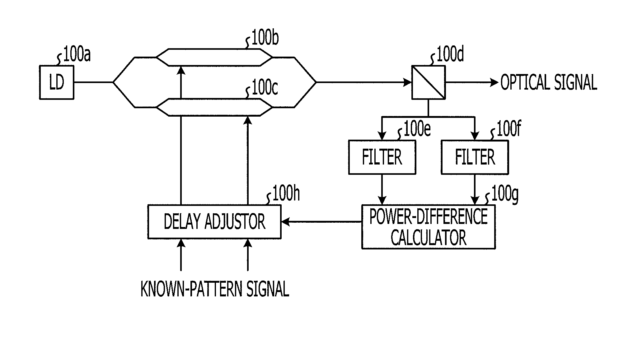
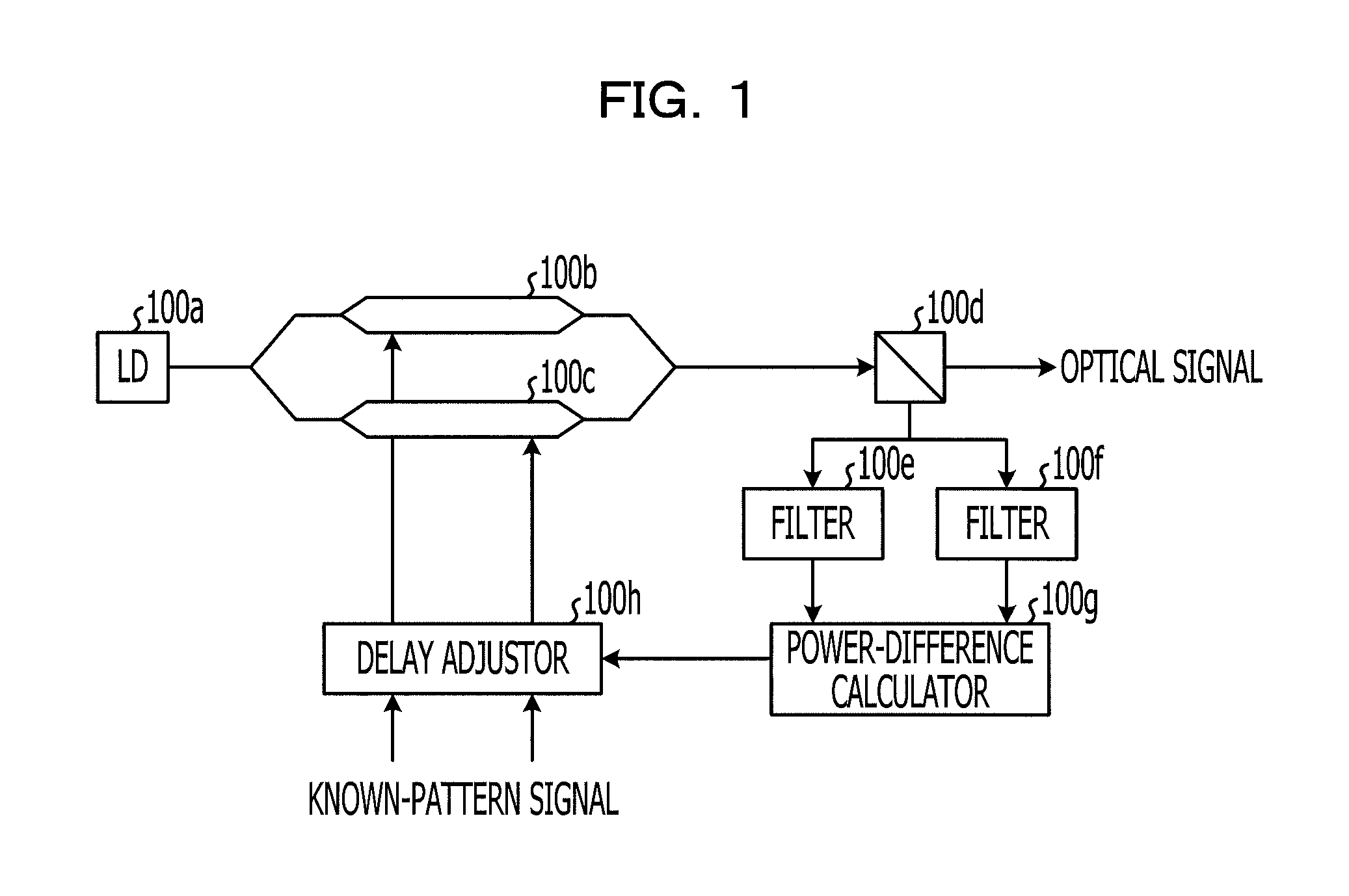
[0046]FIG. 1 is a block diagram illustrating a configuration of an optical modulation apparatus according to a first embodiment. The optical modulation apparatus illustrated in FIG. 1 includes an LD 100a, a first modulator 100b, a second modulator 100c, an optical coupler 100d, filters 100e and 100f, a power-difference calculator 100g, and a delay adjustor 100h.

[0047]The LD 100a serving as a light source emits light of a predetermined wavelength. The first modulator 100b superposes a signal of a known pattern (hereinafter, referred to as a known-pattern signal) on a first component of the light emitted from the LD 100a, whereas the second modulator 100c superposes a known-pattern signal on a second component of the light emitted from the LD 100a. For example, an alternating signal having alternately repeated “0” and “1” serves as one example of the known-pattern signal. When the first modulator 100b and the second modulator 100c are included in a DQPSK modulator for performing DQPS...

second embodiment

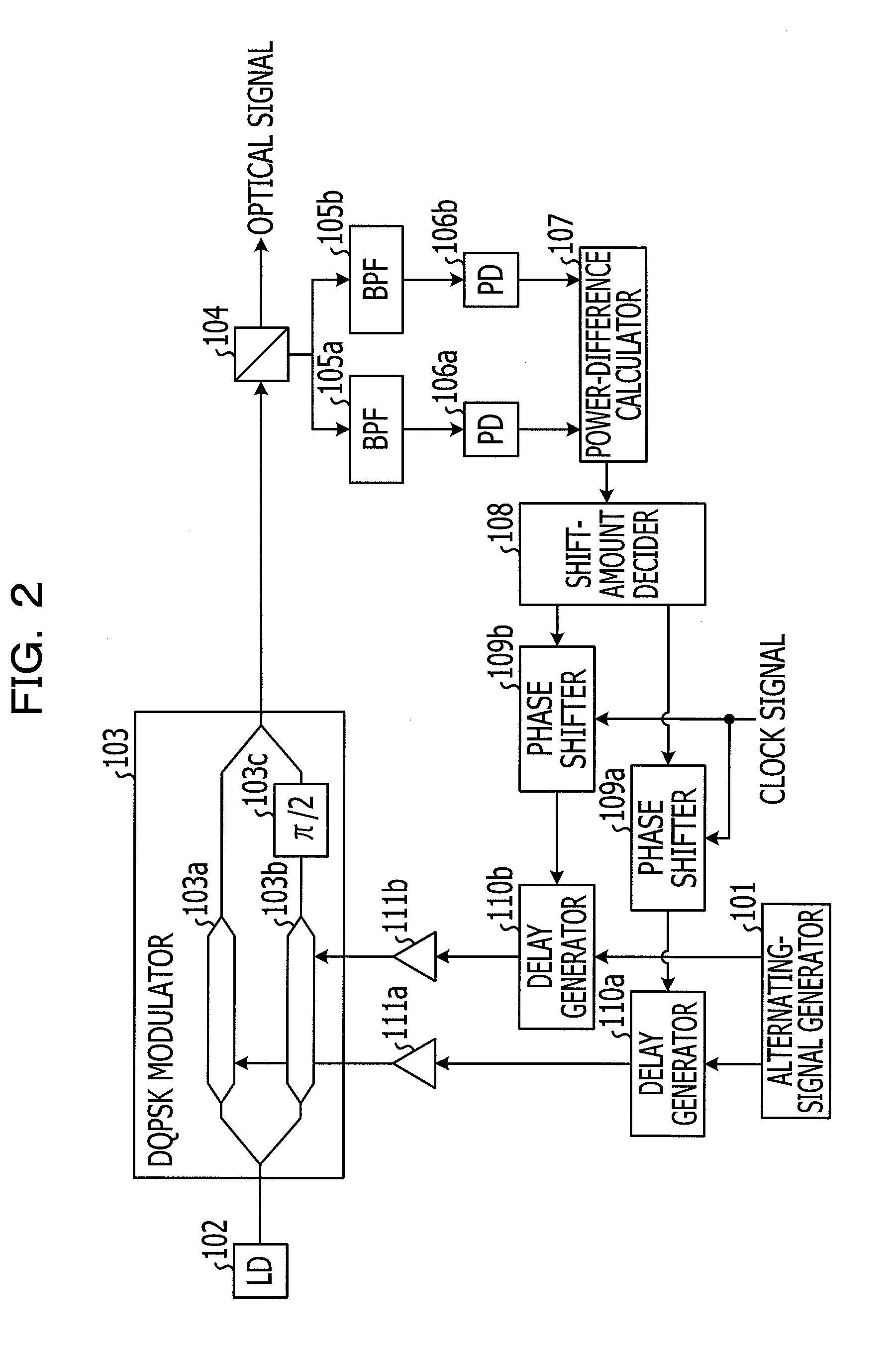
[0055]FIG. 2 is a block diagram illustrating a configuration of an optical modulation apparatus according to a second embodiment. The optical modulation apparatus illustrated in FIG. 2 includes an alternating-signal generator 101, an LD 102, a DQPSK modulator 103, an optical coupler 104, BPFs 105a and 105b, PDs 106a and 106b, a power-difference calculator 107, a shift-amount decider 108, phase shifters 109a and 109b, delay generators 110a and 110b, and DRVs 111a and 111b. Additionally, the DQPSK modulator 103 includes an I-arm modulator 103a, a Q-arm modulator 103b, and a phase shifter 103c.

[0056]The alternating-signal generator 101 generates an alternating signal in which “0” and “1” are alternately repeated. The alternating-signal generator 101 outputs the resulting in-phase alternating signals to the delay generators 110a and 110b. The alternating-signal generator 101 generates the alternating signal at the time of initial booting of the optical modulation apparatus and supplies...

third embodiment

[0081]In a third embodiment, higher-side frequency components and lower-side frequency components are acquired with etalon filters having periodical passbands instead of band-pass filters.

[0082]FIG. 8 is a block diagrams illustrating a configuration of an optical modulation apparatus according to the third embodiment. In FIG. 8, like reference characters designate the same or similar components illustrated in FIG. 2 to omit a description thereof. The optical modulation apparatus illustrated in FIG. 8 includes etalon filters 301a and 301b instead of the BPFs 105a and 105b of the optical modulation apparatus illustrated in FIG. 2.

[0083]The etalon filters 301a and 301b have passbands of the same period called a free spectral range (FSR). Since the etalon filters 301a and 301b have the same FSR but different peak frequencies of the passbands, the etalon filters 301a and 301b have the passbands complementary to each other. For example, as illustrated in FIG. 9, one of the etalon filters ...


PUM

PropertyMeasurementUnit
frequencyaaaaaaaaaa
center frequencyaaaaaaaaaa
poweraaaaaaaaaa

Abstract

An optical modulation apparatus includes a first modulator, a second modulator, a multiplexer, a calculator and an adjustor. The first modulator configured to modulate light emitted by a light source using a first input signal and output a first modulated signal. The second modulator configured to modulate the light using a second input signal and output a second modulated signal. The multiplexer configured to multiplex the first and second modulated signals and output a multiplexed signal. The calculator configured to calculate a power difference between a higher-side frequency component having a frequency higher than a center frequency of the multiplexed signal and a lower-side frequency component having a frequency lower than the center frequency. The adjustor configured to adjust delays of the first and second input signals based on the power.

Description

CROSS-REFERENCE TO RELATED APPLICATIONS[0001]This application is based upon and claims the benefit of priority of the prior Japanese Patent Application No. 2010-64531, filed on Mar. 19, 2010, the entire contents of which are incorporated herein by reference.BACKGROUND[0002]1. Field[0003]Various embodiments described herein relate to optical modulation apparatuses and optical modulation methods.[0004]2. Description of the Related Art[0005]With an increase in transmission traffic, demand has been growing recently for introduction of a next-generation optical transmission system having a transmission capacity exceeding the existing 40 gigabit per second (Gbps). When signal transmission speed is simply increased for realization of the mass transmission capacity, realization of electric signal circuits to be used is difficult. For example, degradation of optical transmission signals, such as spectral degradation caused by optical filters and signal degradation caused by chromatic dispers...

Claims


Application Information

Patent Timeline
Patent Type & Authority Applications(United States)
IPC IPC(8): H04B10/04G02F1/01H04B10/07H04B10/516H04B10/556H04B10/588H04B10/61
CPCH04B10/5162H04B10/505
Inventor NISHIHARA, MASATOTAKAHARA, TOMOOHOSHIDA, TAKESHI
Owner FUJITSU LTD
Why Eureka
Try Eureka