Method and apparatus for forming sand molds via top and bottom pneumatic sand filling perpendicular to the pattern plate

a technology of sand molds and pattern plates, applied in the field of automatic molding machines, can solve the problems of poor filling properties, sand flowability is hindered, and the hardness of the sand mold after compressing may not be uniform, so as to reduce the resistance to sand shooting, reduce maintenance costs, and simplify the structure and manufacturing process.

Active Publication Date: 2019-04-25
HUNTER AUTOMATED MACHINERY
View PDF0 Cites 1 Cited by
  • Summary
  • Abstract
  • Description
  • Claims
  • Application Information

AI Technical Summary

Benefits of technology

[0008]Embodiments of this invention include a passageway body enclosing the sand shooting passageway. The passageway body including a vertical inner side wall adjacent the outlet and a horizontal inner side wall extending at an angle from the vertical inner side wall toward the inlet. An internal tilted arc plate can be used within the passageway to extend between the vertical inner side wall and a horizontal inner side wall, and over an intersection of the vertical inner side wall and the horizontal inner side wall. The tilted arc plate can be used to prevent blockage caused by sand accumulation at dead angles during the long-term work in the sand shooting passageway.
[0009]Embodiments of the present include a sand shooting plate including interchangeable port and cover inserts, arrangeable in custom arrays within the sand shooting plate. In embodiments of this invention, the sand shooting plate includes an upper shooting plate main body and a lower shooting plate, wherein a plurality of sand shooting ports are arranged in an array on the upper shooting plate main body. The back of the sand shooting port processes a sand guiding oblique opening, and the front of the sand shooting port controls the opened and closed sand shooting cover plate. The cover plates are used according to the shape of the work piece to control the array of open sand shooting openings. The sand shooting port of the upper shooting plate can be used to lower resistance against of the sand shooting.
[0010]The present invention further includes a casting gate stick that can be attached to the sand shooting plate, for sprue forming. The casting gate stick can be fixed to cover inserts of the sand shooting plate, and can be composed of a first slightly tapered casting gate stick, a second casting gate stick, a casting gate cup body, a direction guide post and a casting gate sleeve. The first casting gate stick is sleeve-joined in the casting gate cup body, the second casting gate stick is sleeve-joined in the first casting gate stick, the direction guide post is provided at the center of the casting gate sleeve, and the second casting gate stick is provided with a hollow passage that accommodates the reciprocating motion of the direction guide post. The invention thereby provides a body-split structure, and simplifies the structure, processing, and manufacturing process of the casting gate cup body, and reduces the maintenance costs when parts need to be replaced.
[0011]The present invention further includes lifting devices for the upper sand shooting plate. In some embodiments, the lifting device includes a lifting platform and a hydraulic or pneumatic cylinder disposed at the center of the lifting platform. Direction-guiding columns can be distributed around the cylinder, and direction-guiding sleeves that work together with the direction-guiding column help ensure precision in the height adjustment process of the upper sand shooting plate.

Problems solved by technology

Horizontal-type molding machines on the market use side sand shooting, and, especially for a product with a high molded plate height, the sand flowability is hindered due to shielding caused by the pattern plate.
This can result in poor filling property, and the hardness of the sand mold after compressing may not be uniform.
In addition, shapes of existing sand shooting plates provide an undesirable relatively large sand shooting resistance during the sand shooting process.
Abnormal pattern wear, poor green sand cores and surface finish are addition associated issues.

Method used


Image

  • Method and apparatus for forming sand molds via top and bottom pneumatic sand filling perpendicular to the pattern plate
  • Method and apparatus for forming sand molds via top and bottom pneumatic sand filling perpendicular to the pattern plate
  • Method and apparatus for forming sand molds via top and bottom pneumatic sand filling perpendicular to the pattern plate

Examples


Embodiment Construction

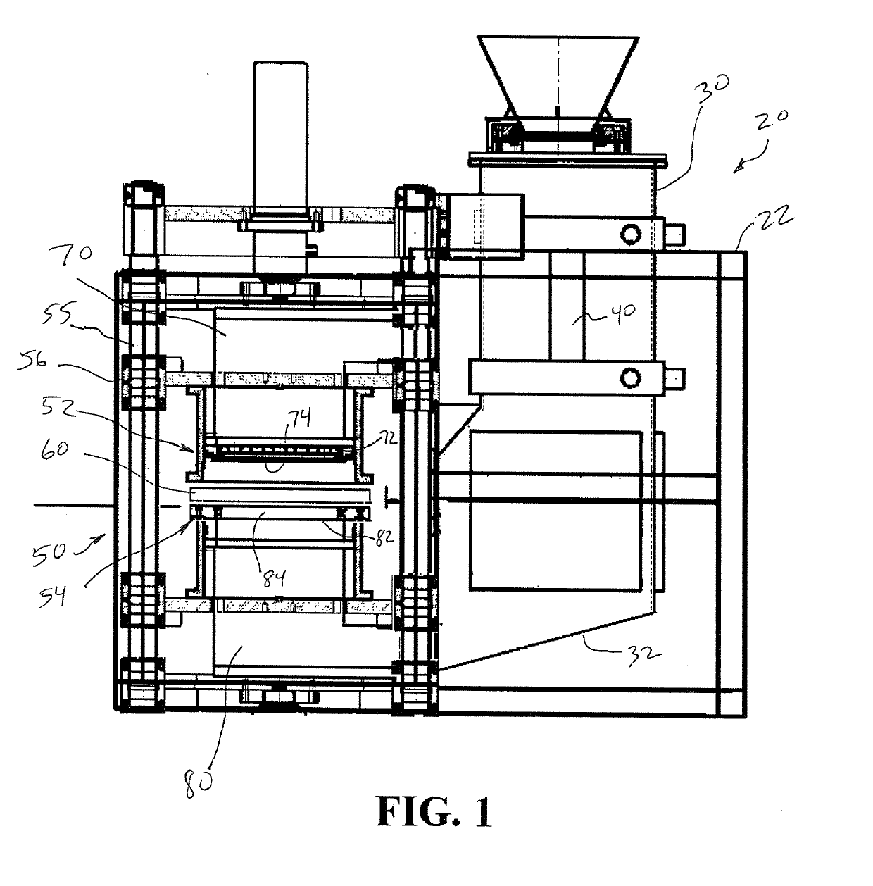
[0028]The present invention provides a sand casting apparatus and method for forming a sand mold about a matchplate pattern. The invention provides an upper and lower sand shooting apparatus, relative to the pattern, for forming both the cope and drag portions of the mold.

[0029]FIG. 1 generally illustrates relevant components of an automatic matchplate molding machine according to one embodiment of this invention. Several components are representatively illustrated, and other details are not shown for ease of explanation, such as components including motors, pumps, tubing / hoses, moveable arms, and cladding and lateral sand containment shielding. Machines of these types are well known to those of ordinary skill in the art and are widely used throughout the foundry industry, such that these additional components of commercial machines do not require illustration. In view of the fact that many of the details of different types of molding machines or other such machines are known and al...


PUM


Abstract

A sand molding apparatus and method, whereby cope and drag portions of a sand mold are formed simultaneously via pressurized sand delivered to each side of a pattern in a perpendicular trajectory. Two opposing sand shooting passageways include a vertical inner side wall and a horizontal inner side wall extending at an angle from the vertical inner side wall. A sand shooting plate at the outlet of each sand shooting passageway includes removable and interchangeable port and cover inserts that can be arranged in custom arrays within the sand shooting plate.

Description

FIELD OF THE INVENTION[0001]This invention relates generally relates to automated molding machines for forming sand molds for use in foundries, and more particularly relates to an apparatus and methods utilizing a pattern plate, a drag flask and a cope flask.BACKGROUND OF THE INVENTION[0002]Metal castings are commonly manufactured at foundries through a molding technique which employs green sand molds comprised of prepared sand and additives which are compressed around cope and drag patterns mounted on opposite sides of a matchplate. The sand mold is thus formed in upper and lower matching portions, an upper cope mold, and a lower drag mold. The cope mold is formed in a separate cope flask which is filled with prepared sand and compacted onto the matchplate. The matchplate is then removed leaving an indentation in the cope mold of the desired shape for the upper portion of the casting. The drag mold is similarly formed in a separate drag flask. Usually the matchplate is in the form ...

Claims


Application Information

Patent Timeline
Patent Type & Authority Applications(United States)
IPC IPC(8): B22C15/24B22C11/00
CPCB22C15/24B22C11/00B22C7/02B22C15/28
Inventor HUNTER, WILLIAM GARYLVTING, HUANG
Owner HUNTER AUTOMATED MACHINERY
Why Eureka
Try Eureka