Stopper apparatus, rotary joint and robot

Active Publication Date: 2019-04-25
ABB (SCHWEIZ) AG
View PDF0 Cites 2 Cited by
  • Summary
  • Abstract
  • Description
  • Claims
  • Application Information

AI Technical Summary

Benefits of technology

[0007]To resolve the problem of small rotation angle of the robot joint, an object of the present invention is to provide a stopper fo

Problems solved by technology

The problem of the foregoing existing technique is that the limit of the operating angle of the turning angle cannot be set to a value in the vicinity of or beyond ±360 degrees.
Further, even if the operating angle is set to a value less than

Method used


Image

  • Stopper apparatus, rotary joint and robot
  • Stopper apparatus, rotary joint and robot
  • Stopper apparatus, rotary joint and robot

Examples


Embodiment Construction

[0043]Hereinafter, solutions as provided the present disclosure will be described in details through embodiments with reference to the accompanying drawings. It should be appreciated that these embodiments are presented only to enable those skilled in the art to better understand and implement the present disclosure, not intended to limit the scope of the present disclosure in any manner.

[0044]Generally, all terms used in the claims are to be interpreted according to their ordinary meaning in the technical field, unless explicitly defined otherwise herein. All references to “a / an / the / said [element, device, component, means, step, etc]” are to be interpreted openly as referring to at least one instance of said element, device, component, means, unit, step, etc., without excluding a plurality of such devices, components, means, units, steps, etc., unless explicitly stated otherwise. Besides, the indefinite article “a / an” as used herein does not exclude a plurality of such steps, units...


PUM


Abstract

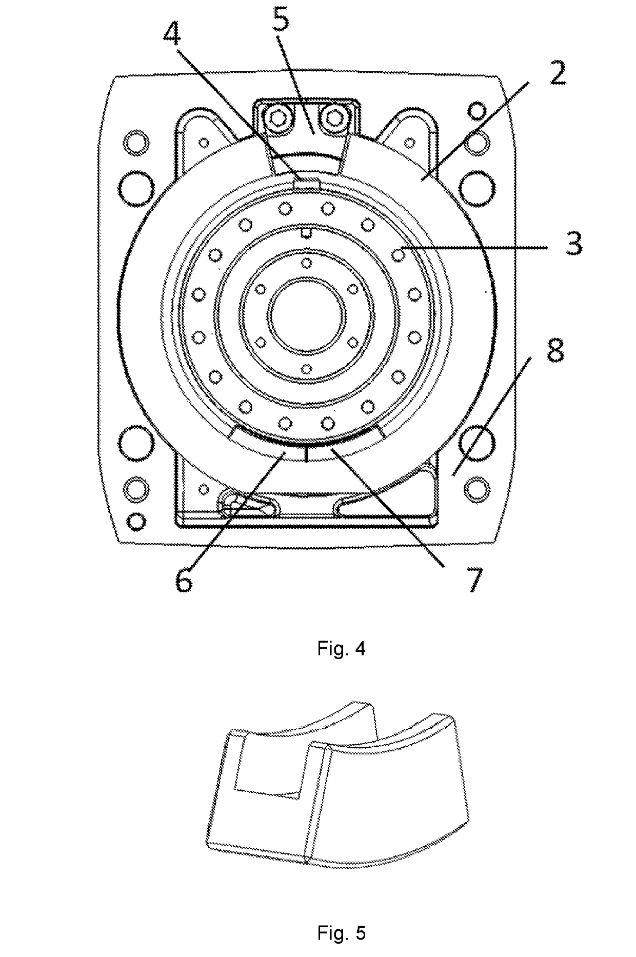
A stopper apparatus for robot rotary joint, for limiting the rotation angle of a turning shaft. The stopper apparatus includes: a rotary protrusion, fixed to the shaft and extended from an outer circumference surface of the shaft; a ring-like orbit, fixed to a mounting housing of the robot rotary joint, inserting the shaft therein; a first slider and a second slider, rotatably accommodated in the orbit and able to push each other to rotate; a stop protrusion, fixed to the housing of a robot rotary joint and extended in the direction of the center of the shaft; the rotary protrusion is able to directly push the second slider to rotate, while it is not able to directly push the first slider to rotate; the shaft, the rotary protrusion and the second slider cannot be obstructed by the stop protrusion when rotate, while the first slider is able to be obstructed by the stop protrusion when rotate, thereby the relative rotation between the shaft and the housing can be stopped. The present invention also provides a rotary joint and a robot. Compared with the existing prior arts, the proposed solution enables a rotation range larger than ±360 degrees.

Description

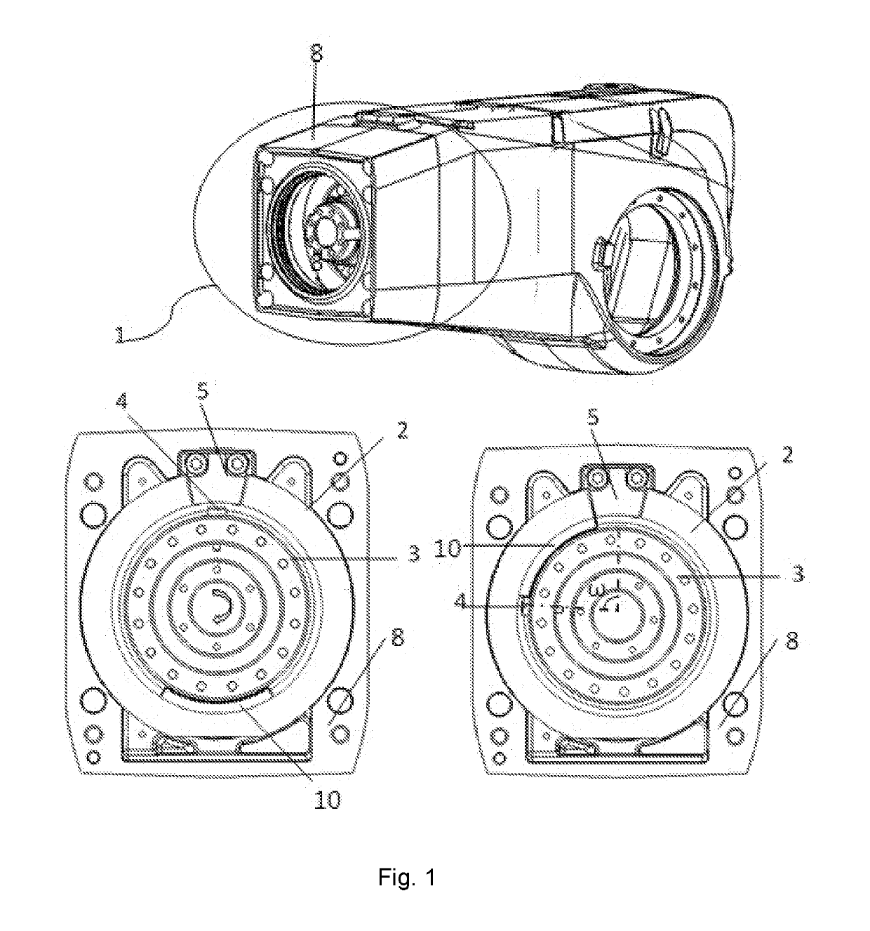
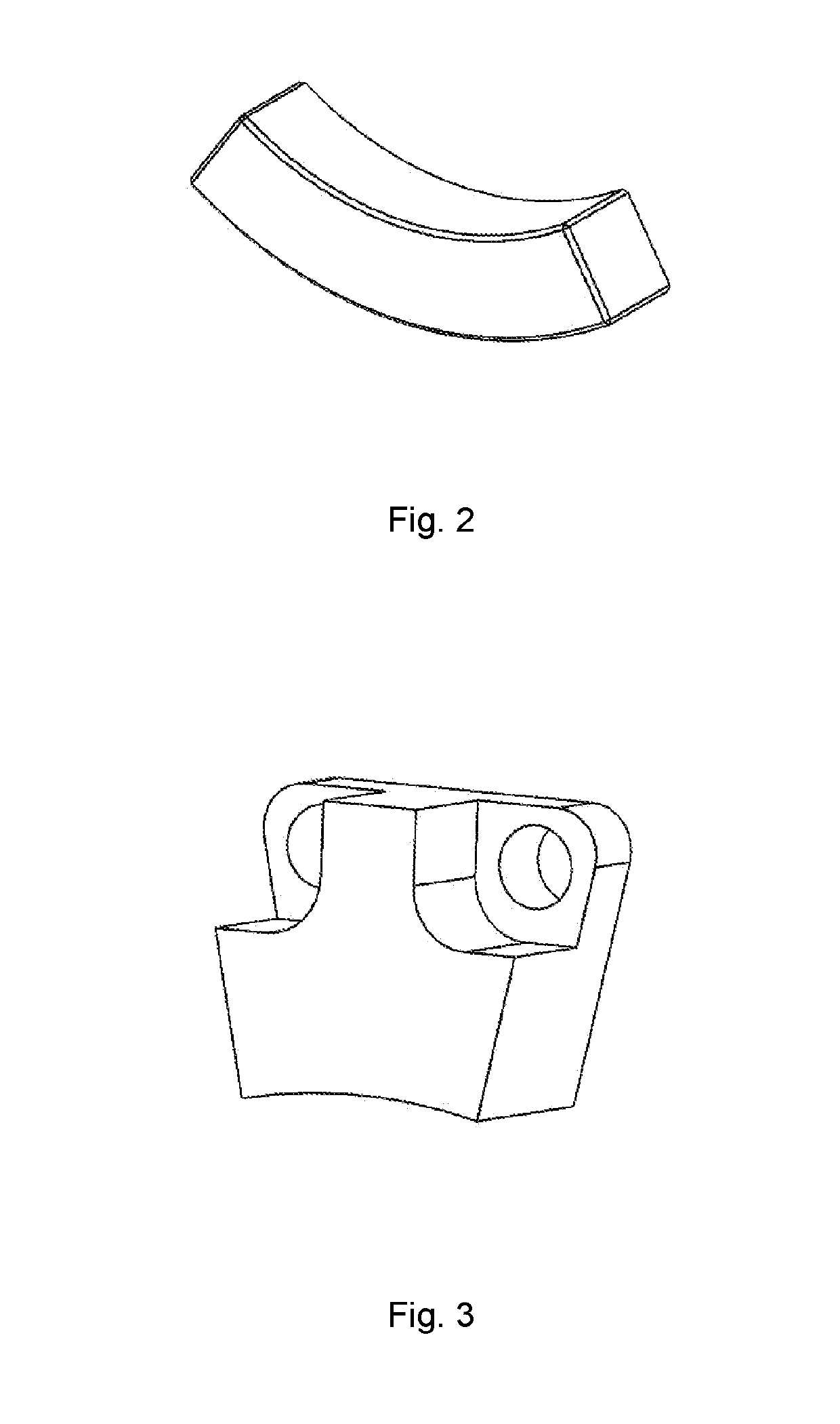
FIELD OF THE INVENTION[0001]Embodiments of the present disclosure generally relate to a stopper apparatus, and particularly relate to a stopper apparatus for use in a rotary joint, a rotary joint and a robot comprising the rotary joint.BACKGROUND OF THE INVENTION[0002]A commonly used multi-axis industrial robot includes a mounting cover, a turning flange which turns around an axis over the mounting cover, and a robot arm which is mounted on the turning flange. A stopper is attached to the mounting cover and the turning flange for the purpose of mechanically limiting the operating angle of the turning flange when the rotation angle reaches a preset limit.[0003]As shown in FIG. 1, a mechanical stopper is installed on the robot housing unit 1 of a rotary joint. A circular orbit 2 and a stop dog 5, which is further shown in FIG. 2, are installed on a cover 8, which is fixed on the robot body by bolts. A single slider 10, which is further shown in FIG. 3, is placed between the circular o...

Claims


Application Information

Patent Timeline
IPC IPC(8): B25J9/10B25J17/00
CPCB25J9/101B25J17/00
Inventor SHA, JIAJIECAO, XIAODONGCAO, KAIYUANHA, YUNZHU, ZHU
Owner ABB (SCHWEIZ) AG
Why Eureka
Try Eureka