Machinery system intended for the manipulation of at least one upper module and/or at least one lower module

Active Publication Date: 2019-04-25
AIRBUS SAS
View PDF0 Cites 0 Cited by
  • Summary
  • Abstract
  • Description
  • Claims
  • Application Information

AI Technical Summary

Benefits of technology

[0005]An object of the present invention is to mitigate these drawbacks by proposing a machinery system contribut

Problems solved by technology

Moreover, it does not allow more than one module to be manipulated at a

Method used


Image

  • Machinery system intended for the manipulation of at least one upper module and/or at least one lower module
  • Machinery system intended for the manipulation of at least one upper module and/or at least one lower module
  • Machinery system intended for the manipulation of at least one upper module and/or at least one lower module

Examples


Example

[0043]The rest of the description will refer to the figures cited above.

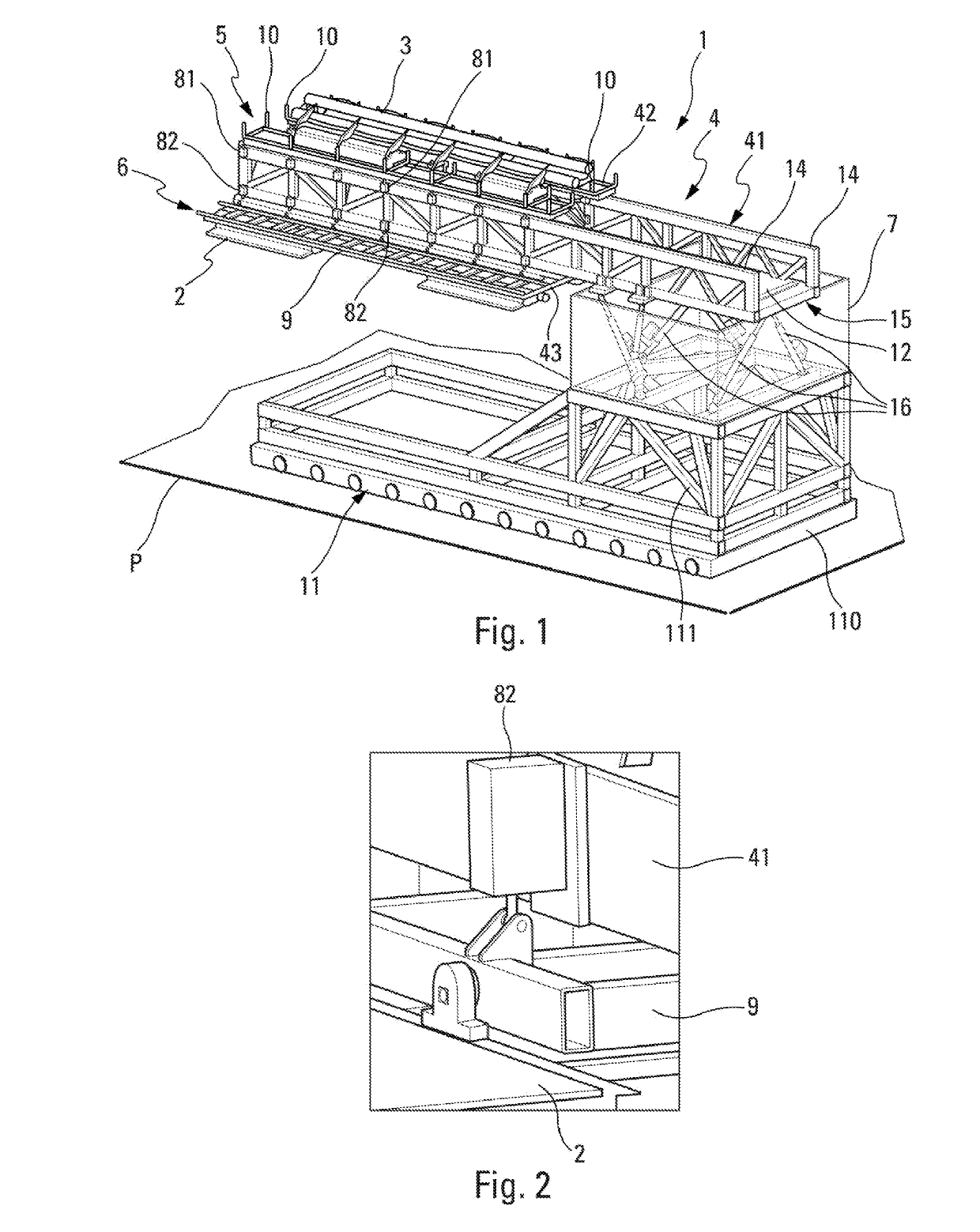
[0044]FIG. 1 represents an embodiment of the machinery system 1 configured for the manipulation of modules 2, 3.

[0045]The machinery system 1 is mobile.

[0046]It makes it possible to manipulate, on a displacement surface P, for example a horizontal plane, in particular:

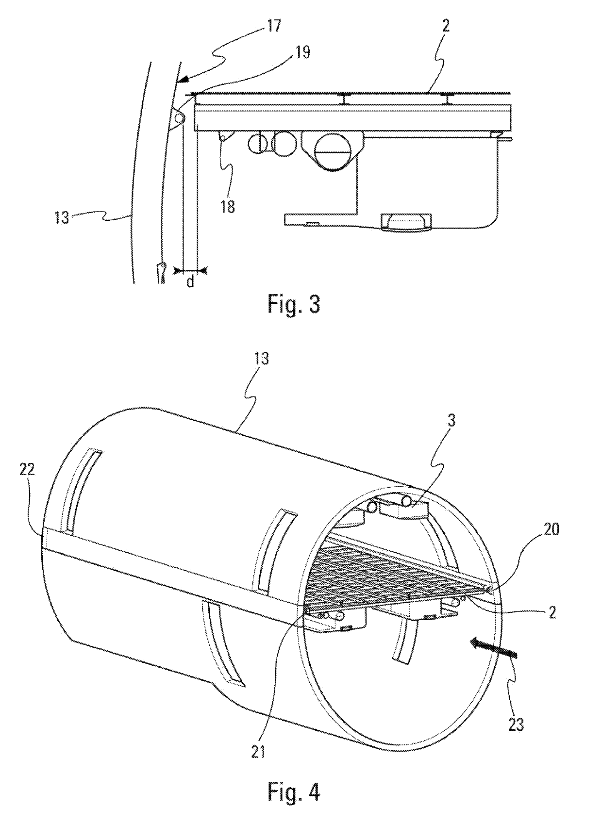
[0047]at least one upper module 3 or at least one lower module 2 to be introduced into a housing 13, such as an airplane fuselage,

[0048]or else, at least one upper module 3 and at least one lower module 2 to be introduced into a housing 13.

[0049]A lower module 2 can correspond to an aircraft floor.

[0050]An upper module 3 can correspond to an upper part (“crown”) fixed to the top of a fuselage 13 allowing technical ducts or wiring to be run in the fuselage 13.

[0051]The machinery system 1 comprises a securing device 7 and an arm 4 mounted cantilever-fashion on the securing device 7 of the arm 4. The arm 4 is configured to be introduced into the housin...


PUM


Abstract

The machinery system comprises an arm having an upper fixing device arranged to fix to the arm at least one upper module to be manipulated in an upper plane and a lower fixing device arranged to fix to the arm at least one lower module to be manipulated in a lower plane; a first securing device of the arm configured to control the positioning of the arm; the arm being mounted cantilever-fashion on the first securing device. The machinery system makes it possible to at least halve the manipulation time for two modules by virtue of the arm mounted cantilever-fashion, to which two modules can be fixed.

Description

CROSS-REFERENCES TO RELATED APPLICATIONS[0001]This application claims the benefit of the French patent application No. 1760040 filed on Oct. 24, 2017, the entire disclosures of which are incorporated herein by way of reference.TECHNICAL FIELD[0002]The present invention relates to a machinery system for the manipulation of at least two modules on a surface.BACKGROUND OF THE INVENTION[0003]Assembling an aircraft can include the precise manipulation of modules in confined and narrow housings. Generally, this manipulation of modules requires the assembly and dismantling of systems allowing this manipulation.[0004]The document FR 3 048 235 describes a machinery system allowing the manipulation of modules, such as the introduction of a floor into an aircraft fuselage. This machinery system requires the assembly and the dismantling of upper beams in the aircraft, the assembly and the dismantling of lower beams on the module to be introduced and the assembly and the dismantling of support e...

Claims


Application Information

Patent Timeline
IPC IPC(8): B64F5/10B64F5/50
CPCB64F5/10B64F5/50B66F9/0755B66C19/00B64C1/18B64D2221/00
Inventor BRINDEAU, JEAN-MICKAELAQUILA, ANDRE
Owner AIRBUS SAS
Why Eureka
Try Eureka