

Hammer bit
- Summary
- Abstract
- Description
- Claims
- Application Information
AI Technical Summary
Benefits of technology
Problems solved by technology
Method used
Image

Examples
first embodiment
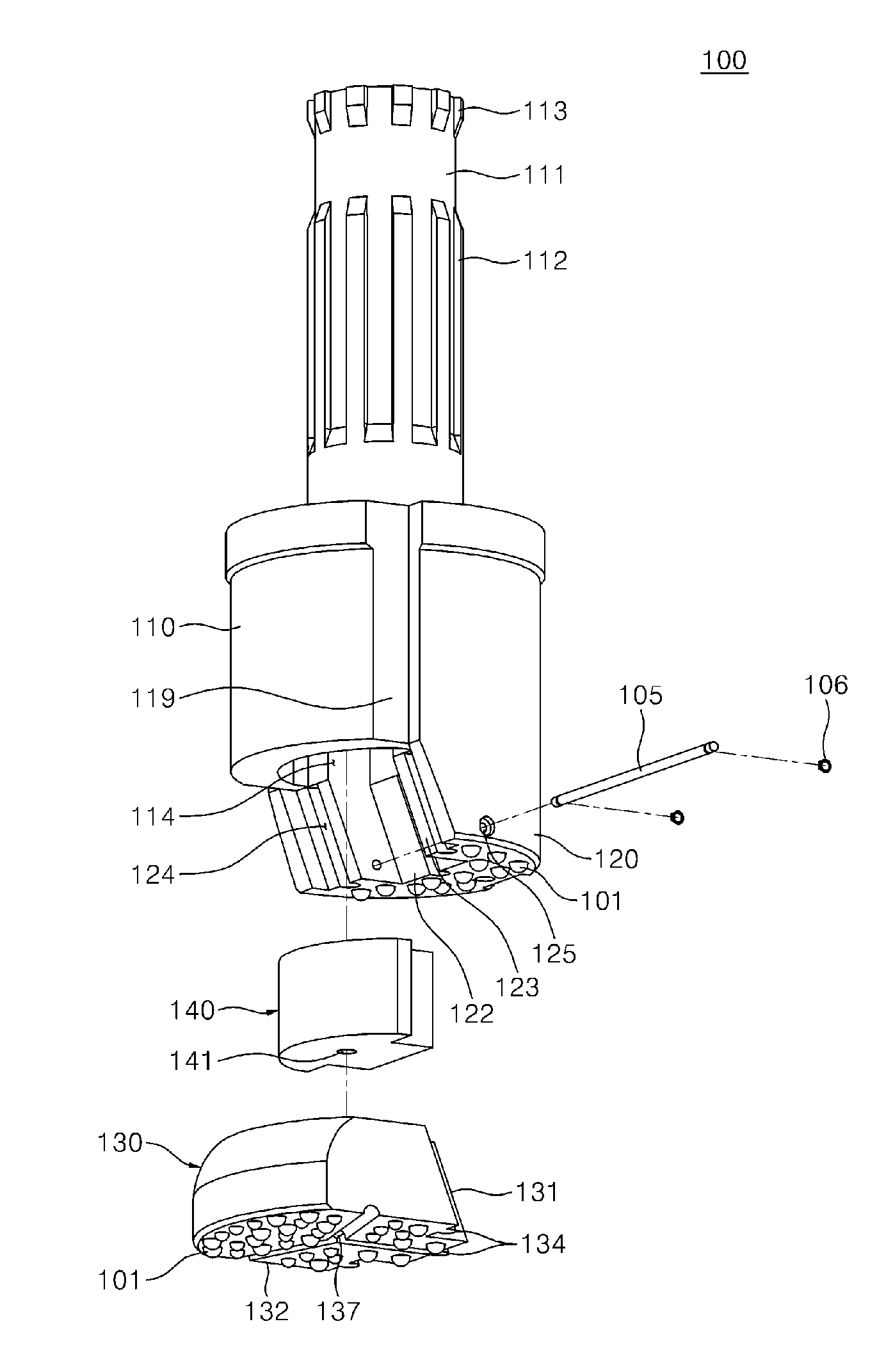
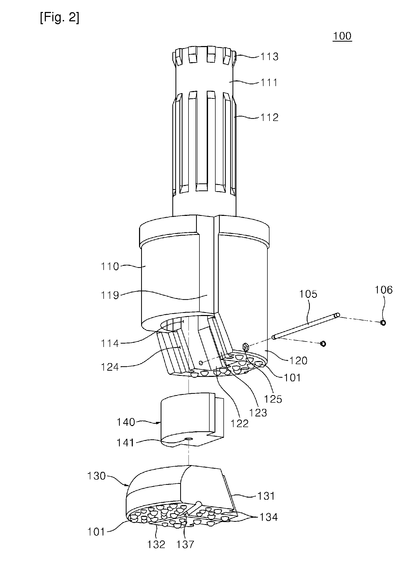
[0053]FIG. 2 is an exploded perspective view of the hammer bit illustrated in FIG. 2 and FIG. 3 is a perspective view of a wing bit of the hammer bit of FIG. 2.
[0054]Referring to FIGS. 2 and 3, the hammer bit 100 includes a bit body 110, a housing bit 120, and a wing bit 130. A plurality of crushing protrusions 101 may be formed on undersurfaces of the housing bit 120 and wing bit 130. The crushing protrusions 101 may be formed of tungsten carbide or industrial diamond that is excellent in an abrasion-resistance and a heat-resistance.
[0055]The bit body 110 includes a coupling portion 111 so that it can be coupled to the hammer drill 10. The coupling portion 111 includes a spline portion 112 and a ring portion 113 for lifting the hammer bit 100 so as to rotate by receiving an external force from the hammer drill 10.
[0056]The spline portion 112 may be formed by grooves and protrusions that are alternately arranged in parallel with a length direction of the bit body 110. In addition, t...
second embodiment
[0077]The following will describe the hammer bit of the present invention.
[0078]FIG. 8 is an exploded perspective view of a second embodiment of a hammer bit of the present invention.
[0079]Referring to FIG. 8, a hammer bit 200 includes a bit body 210 and a housing bit 220 disposed under the bit body 210. At least two wing bits 230 are installed on the housing bit 220. At this point, at least two slope portions 222 are formed on the housing bit 220 such that the slope portions 222 are converged toward a central portion of the housing bit 220.
[0080]The bit body 210 is provided with a guide groove 214 corresponding to the upper portion of each of the wing bits 230. A spacer 240 may be coupled to each of the guide grooves 214 to move up and down together with the wing bit 230. The spacer 240 fills up the upper space of the wing bit 230 as it moves down together with the wing bit 230.
[0081]In addition, the spacer 240 is sized to fully cover an outer side of a top surface of the wing bit ...
third embodiment
[0087]The following will describe a hammer bit of the present invention.
[0088]FIG. 10 is an exploded perspective view of a third embodiment of a hammer bit according to the present invention.
[0089]Referring to FIG. 10, a hammer bit 300 includes a bit body 310, a housing bit 320, and a wing bit 330. A plurality of crushing protrusions 301 may be formed on undersurfaces of the housing bit 320 and wing bit 330. The crushing protrusions 301 may be formed of tungsten carbide or industrial diamond that is excellent in an abrasion-resistance and a heat-resistance.
[0090]The bit body 310 includes a coupling portion 311 so that it can be coupled to the hammer drill 10. The coupling portion 311 includes a spline portion 312 and a ring portion 313 for lifting the hammer bit 300 so as to rotate by receiving an external force from the hammer drill 10.
[0091]The spline portion 312 may be formed by grooves and protrusions that are alternately arranged in parallel with a length direction of the bit b...
PUM
 Abstract
Description
Claims
Application Information