Vehicle, battery unit and battery carrying method of vehicle

Inactive Publication Date: 2017-09-21
HONDA MOTOR CO LTD
View PDF4 Cites 4 Cited by
  • Summary
  • Abstract
  • Description
  • Claims
  • Application Information

AI Technical Summary

Benefits of technology

[0018]According to the structure of (1), the first power storage element and the second power storage element are disposed outside the passenger compartment and located under the passenger compartment along a vertical direction, such that a space inside the passenger compartment is wide, and the first power storage element and the second power storage element can be integrally installed, so as to reduce an assembling time required for assembling the power storage elements to a vehicle body. Moreover, since the first power storage element and the second power storage element do not require a respective cooling loop, miniaturization of the system becomes possible. Moreover, since the second power storage element is disposed in front of the first power storage element, even if only a driving wind is adopted to cool the first power storage element and the second power storage element, the driving wind used for cooling the second power storage element with less heating amount can be used for cooling the first power storage element with more heating amount. Therefore, compared to the situation of conducting the cooling in an inverse sequence, the two power storage elements can be effectively cooled down.
[0019]According to the structure of (2), the first power storage element and the second power storage element are accommodated in the same frame, such that the assembling time required for assembling the first power storage element and the second power storage element to the vehicle body can be greatly reduced. Moreover, by making a refrigerant to flow inside the frame, the first power storage element and the second power storage element can be easily cooled.
[0020]According to the structure of (3), after the second power st

Problems solved by technology

Therefore, a problem of assembli

Method used


Image

  • Vehicle, battery unit and battery carrying method of vehicle
  • Vehicle, battery unit and battery carrying method of vehicle
  • Vehicle, battery unit and battery carrying method of vehicle

Examples


first embodiment

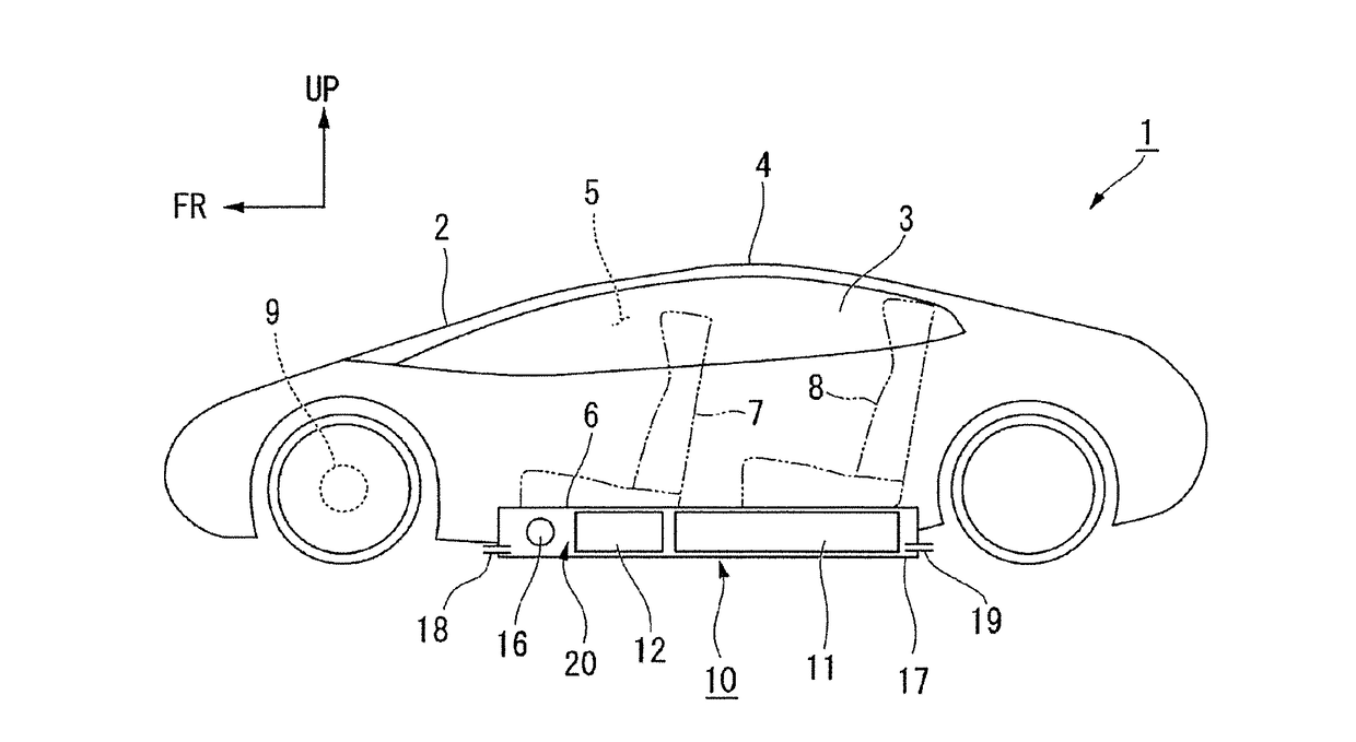
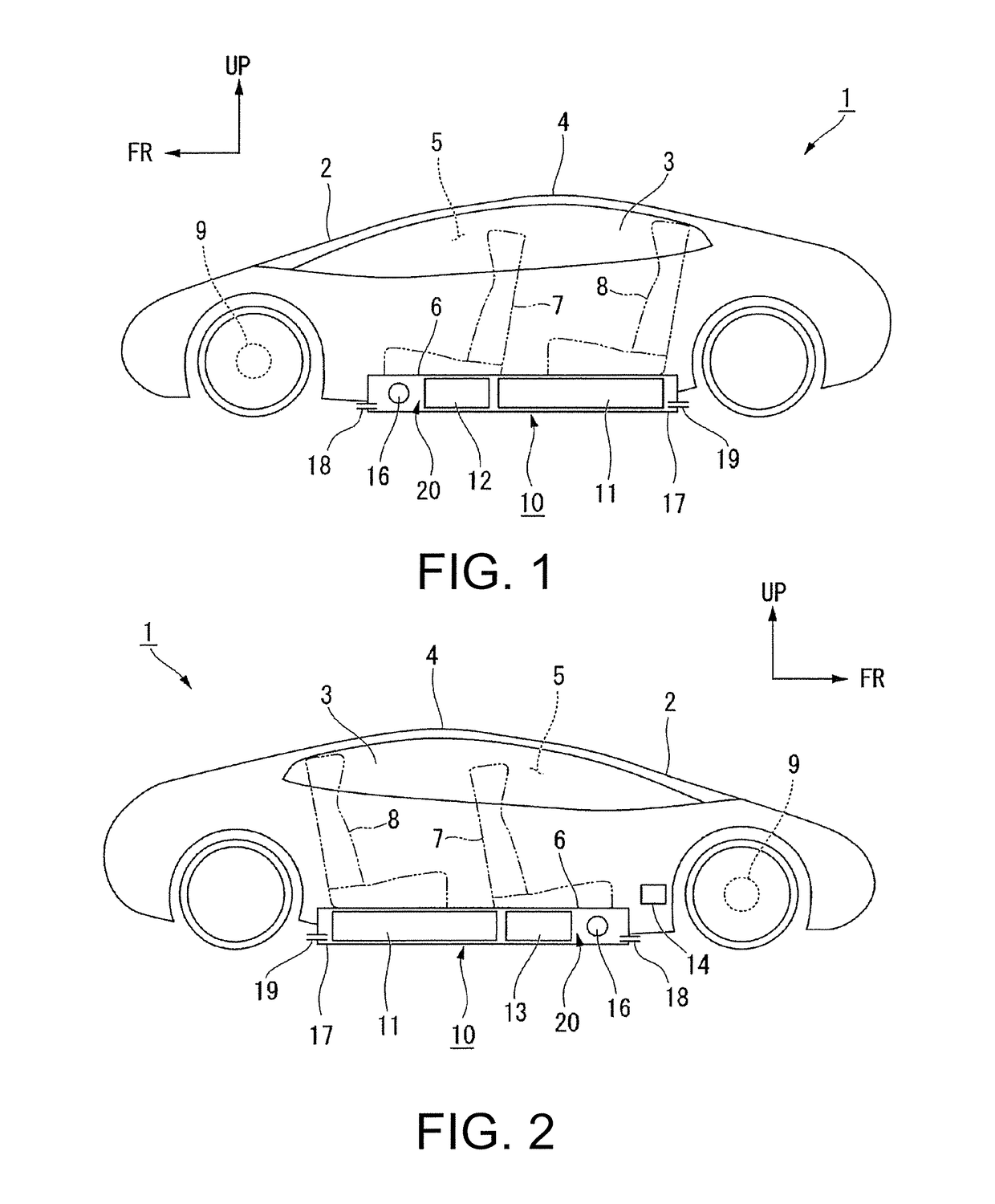
[0037]As shown in FIG. 1, the vehicle 1 has a passenger compartment 5 encircled by a front window glass 2, left and right side window glass 3, and a roof 4. The vehicle 1 has a front seat 7 and a back seat 8 for passengers on a floor panel 6 and in the passenger compartment 5.

[0038]The vehicle 1 is an electric vehicle (EV), which has a motor (a driving element) 9 used for driving and a battery (a first power storage element 11 and a second power storage element 12). The motor 9 is driven by electric power of at least one of the first power storage element 11 and the second power storage element 12. Besides an alternating current (AC) motor or a direct current (DC) motor disposed in an engine room located at a front portion of the vehicle body, the motor 9 can also be an in wheel motor. Besides that the vehicle 1 is a battery type EV only using the energy of the battery to drive the motor 9, the vehicle 1 can also be a hybrid car using both of electricity and an engine (internal comb...

second embodiment

[0063]Then, the second embodiment of the invention is described below with reference of FIG. 5.

[0064]Compared to the first embodiment, a difference of a vehicle 30 and a battery unit 35 of the present embodiment is that an evaporator 31 is configured at the external gas inlet port 18. Other structures that are the same or similar to that of the aforementioned embodiment are denoted by the same reference numbers, and descriptions of the same technical contents are omitted.

[0065]The evaporator 31 is, for example, a heat exchanger using an air conditioning refrigerant of the vehicle 30 to cool the air, and is disposed in the frame 17 close to the back (a downstream side) of the external gas inlet port 18, and is disposed in front of (an upstream side) each of the power storage elements 11 and 12. In the example of FIG. 5, the fan 16 is disposed between the evaporator 31 and each of the power storage elements 11 and 12. Through the external gas inlet port 18, the external gas outlet por...

third embodiment

[0066]Then, the third embodiment of the invention is described below with reference of FIG. 6.

[0067]Compared to the first embodiment, a difference of a vehicle 40 and a battery unit 45 of the present embodiment is that the frame 17 has an indoor gas inlet port 41 and an indoor gas outlet port 42 opening towards the passenger compartment 5 to replace the external gas inlet port 18 and the external gas outlet port 19. Other structures that are the same or similar to that of the aforementioned embodiment are denoted by the same reference numbers, and descriptions of the same technical contents are omitted.

[0068]In the dame 17, the air in the passenger compartment 5 can be inlet from the indoor gas inlet port 41, and after the second power storage element 12 and the first power storage element 11 are sequentially cooled by the air, the air is exhausted to the passenger compartment 5 through the indoor gas outlet port 42. Through the indoor gas inlet port 41, the indoor gas outlet port 4...


PUM


Abstract

A vehicle adapted to improve cooling capacity and a carrying capacity of two types of batteries and implementing miniaturization of a system including the batteries, a battery unit and a battery carrying method of the vehicle are provided. The vehicle (1) includes a first power storage element (11), a second power storage element (12) with output weight density superior to that of the first power storage element (11), a motor (9) driven by at least one of electric powers of the first and second power storage elements (11) and (12), where the first and second power storage elements (11) and (12) are disposed outside a passenger compartment (5) and disposed under the passenger compartment (5) along a vertical direction, and the second power storage element (12) is disposed at a front end along a front and rear direction of the vehicle compared to the first power storage element (11).

Description

CROSS-REFERENCE TO RELATED APPLICATION[0001]This application claims the priority benefit of Japan application serial no. 2016-051500, filed on Mar. 15, 2016. The entirety of the above-mentioned patent application is hereby incorporated by reference herein and made a part of this specification.BACKGROUND OF THE INVENTION[0002]Field of the Invention[0003]The invention relates to a vehicle, a battery unit and a battery carrying method of a vehicle.[0004]Description of Related Art[0005]A vehicle having two driving batteries with different characteristics (for example, different charging capacities, etc.) has been developed, for example, in a patent literature 1, in the aforementioned vehicle, the two batteries are disposed at different positions of a vehicle body. Namely, a high-output type battery is disposed in a luggage trunk, and a high-capacity type battery is disposed outside a passenger compartment and is disposed on a bottom surface of the vehicle body.EXISTING TECHNICAL LITERAT...

Claims


Application Information

Patent Timeline
IPC IPC(8): B60L11/18B60L15/00H01M2/10H01M10/663H01M10/613H01M10/6562H01M10/6568B60K1/04H01M10/625H01M50/204H01M50/249
CPCB60L11/1877B60K1/04B60L15/007B60L11/1874H01M2/1083H01M10/625H01M2220/20H01M10/6562H01M10/6568H01M10/663B60K2001/0422B60K2001/0433H01M10/613H01M10/42B60L50/64H01M50/249H01M50/204B60K11/02B60K2001/005B60K2001/0438B60L58/26B60L50/66Y02T10/64Y02T10/70Y02E60/10
Inventor TAKIZAWA, DAIJIROOGUMA, HIROKAZU
Owner HONDA MOTOR CO LTD
Why Eureka
Try Eureka