Spool for winding optical fiber

Active Publication Date: 2006-11-21
SAMSUNG ELECTRONICS CO LTD
View PDF9 Cites 2 Cited by
  • Summary
  • Abstract
  • Description
  • Claims
  • Application Information

AI Technical Summary

Benefits of technology

[0010]According to the present invention, a spool for winding an optical fiber comprises flanges attached to each other using an ultrasonic fusion splicer, thereby reducing assembly time and improving productivit

Problems solved by technology

However, the heating process for welding the flanges 1a, 1b complicates assembly of the spool 1.
Further, it is impossible to disassemble the spool for re-welding if the flanges 1a

Method used


Image

  • Spool for winding optical fiber
  • Spool for winding optical fiber
  • Spool for winding optical fiber

Examples


Example

[0022]Preferred embodiments of the present invention will be described in detail with reference to the annexed drawings.

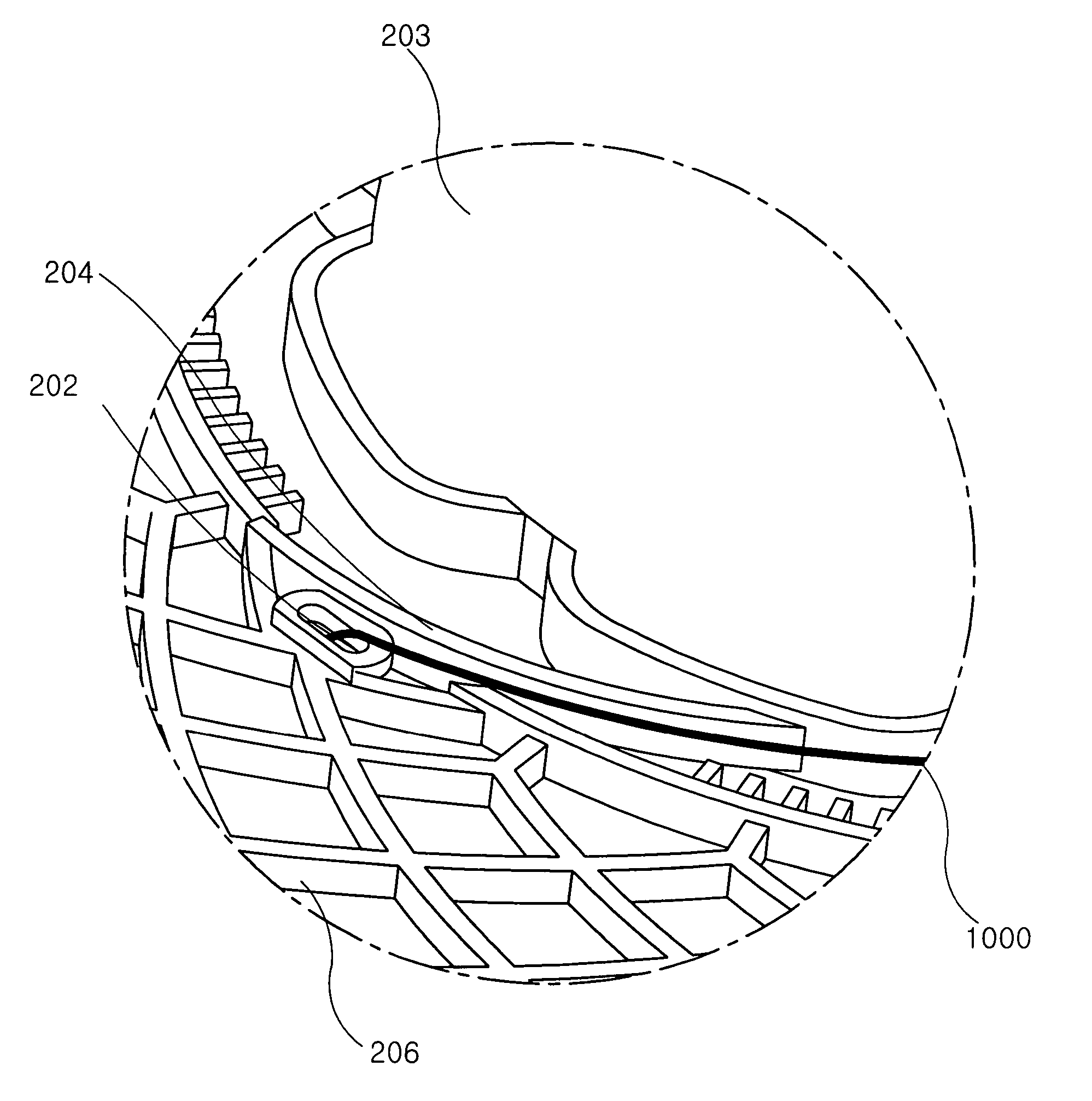
[0023]As shown in FIGS. 4 to 8, a spool assembly 100 for winding an optical fiber 1000 comprises first and second flanges 200, 300, and first and second cylindrical barrels 201, 301, on which the optical fiber 1000 is wound. A junction is formed by mutually engaging the first and second cylindrical barrels 201, 301 in an axial direction face-to-face and fusing the barrels together. The first and second flanges 200, 300 are formed in the shape of concentric disks that sandwich and protrude radially from the first and second cylindrical barrels 201, 301 to restrict the winding area of the optical fiber 1000. The first and second flanges 200, 300 include subsidiary barrels 203, 303 and are sandwiched by and formed integrally with the subsidiary barrels 203, 303 to assist in the proper winding of the optical fiber 1000 onto the spool assembly 100. A start end of the op...


PUM

PropertyMeasurementUnit
Shapeaaaaaaaaaa
Areaaaaaaaaaaa

Abstract

A spool for winding an optical fiber includes flanges attached to each other using an ultrasonic fusion splicer. The spool has first and second cylindrical barrels, on which the optical fiber is wound. The flanges have a disk shape and protrude radially from the first and second cylindrical barrels so as to restrict the winding area of the optical fiber. Ultrasonic fusion splicing points form along a junction by engaging the first and second cylindrical barrels in an axial direction so as to face each other, locating a head of an ultrasonic fusion splicer on the junction and generating an ultrasonic wave from the head to the junction so as to fusion splice the first and second flanges together.

Description

CLAIM OF PRIORITY[0001]This application claims priority to an application entitled “SPOOL FOR WINDING OPTICAL FIBER,” filed in the Korean Intellectual Property Office on Dec. 6, 2002 and assigned Serial No. 2002-77170, the contents of which are hereby incorporated by reference.BACKGROUND OF THE INVENTION[0002]1. Field of the Invention[0003]The present invention relates to a spool for winding an optical fiber, and more particularly to a spool for winding an optical fiber comprising flanges attached to each other using an ultrasonic fusion splicer.[0004]2. Description of the Related Art[0005]Recently, in order to construct an information super-highway, there is a great demand for optical fibers which are used as optical signal transmission media in optical communication systems. They are typically wound on a spool and may be provided with coating layers on their outer circumferences or may be uncoated. The spool for winding an optical fiber comprises a set of spool bodies, each body f...

Claims


Application Information

Patent Timeline
IPC IPC(8): B65H75/14G02B6/00B29C65/00B29C65/08B29C65/58B65H75/06B65H75/28B65H75/50C03B37/03
CPCB29C65/08B29C66/225B29C66/54B65H75/14B65H75/50B29C66/8322B29C66/81422B29C65/58B29L2031/704B29C66/71B29K2077/00B29K2059/00B29K2055/02B29C66/1142B29C66/73921B65H75/06
Inventor JEONG, CHANG-WOONGLEE, YEONG-SEOPJUNG, KI-TAE
Owner SAMSUNG ELECTRONICS CO LTD
Why Eureka
Try Eureka