Redundant storage system and failure recovery method in redundant storage system

Inactive Publication Date: 2019-04-25
HITACHI LTD
View PDF2 Cites 3 Cited by
  • Summary
  • Abstract
  • Description
  • Claims
  • Application Information

AI Technical Summary

Benefits of technology

[0009]According to the present invention, when failure is generated, the accuracy of determining whether a controller among a plurality of controllers is to be blocked is improved, while

Problems solved by technology

Typically, when a failure occurs in any controller, a redundant storage system may pass into a state where it cannot be determined which controller has failed and induced overall system failure (hereinafter called ‘failure mode’).
Here, even if one normal con

Method used


Image

  • Redundant storage system and failure recovery method in redundant storage system
  • Redundant storage system and failure recovery method in redundant storage system
  • Redundant storage system and failure recovery method in redundant storage system

Examples


first embodiment

(1) First Embodiment

[0019](1-1) Configuration of Redundant Storage System According to the First Embodiment.

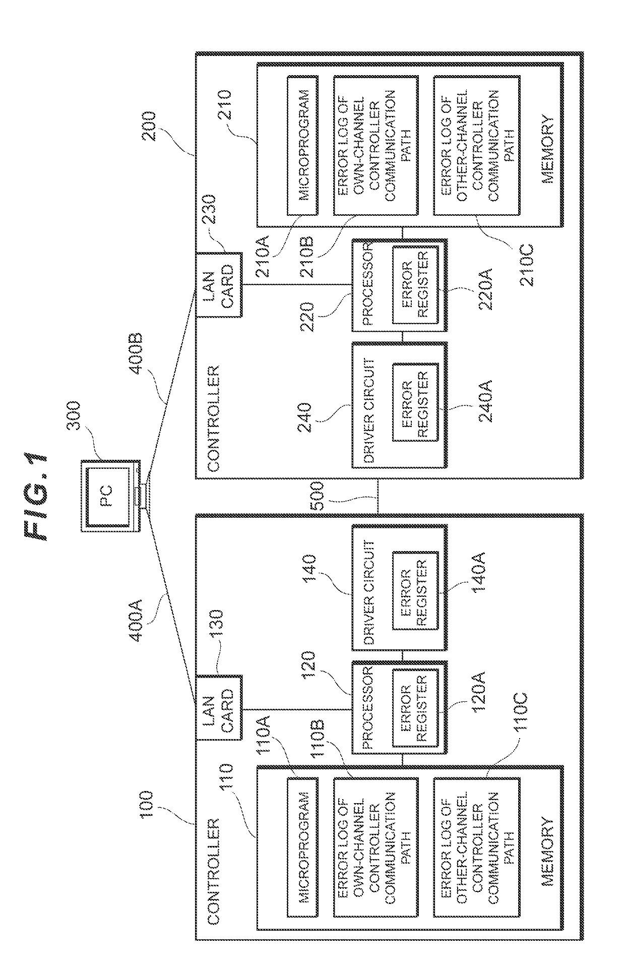
[0020]FIG. 1 shows a schematic configuration of a redundant storage system according to the first embodiment.

[0021]The redundant storage system according to the first embodiment comprises a first controller 100 and a first storage apparatus which is not shown, a second controller 200 and a second storage apparatus which is not shown, and a PC 300. The first controller 100 is connected to the PC 300 via a LAN card 130 by means of a network 400A, whereas the second controller 200 and PC 300 are connected via a LAN card 230 by means of a network 400B.

[0022]The PC 300 is a computer that is operated by a maintenance worker and which outputs instructions to write and read data to the first controller 100 and the second controller 200 according to an operation by the maintenance worker.

[0023]The first controller 100 controls the reading and writing of data from / to the first storage a...

second embodiment

(2) Second Embodiment

[0090]The redundant storage system according to the second embodiment is configured in much the same way as the redundant storage system according to the first embodiment and executes the same operations, and hence in the ensuring explanation, the points of difference between the two redundant storage systems will be explained.

[0091](2-1) Features of the Second Embodiment

[0092]The redundant storage system according to the second embodiment differs from the first embodiment in that the first controller 100 and the second controller 200 each execute faulty controller specification processing. Specific details are explained hereinbelow.

[0093](2-2) Faulty Controller Specification Processing

[0094]FIG. 8 is a sequence chart showing an example of faulty controller specification processing using failure information. Note that, in the drawing, when the reference signs are the same as the reference signs in FIG. 4 and the like, this indicates the same processing.

[0095]Whe...


PUM


Abstract

A plurality of controllers continuously perform by degenerating communication between the controllers by using a portion of the controller communication path even when it is determined that one controller among the plurality of controllers is to be blocked, while, when it is determined as a result of the block determination that the one controller is to be blocked but the block determination is erroneous, the new controller is synchronized to the reinstalled one controller by using the most recent system control information which was last synchronized, in response to the new controller being installed in place of the one controller.

Description

TECHNICAL FIELD[0001]The present invention relates to a redundant storage system and a failure recovery method in the redundant storage system, and more particularly can be suitably applied to a redundant storage system in which a plurality of controllers are interconnected via controller communication paths.BACKGROUND ART[0002]Typically, when a failure occurs in any controller, a redundant storage system may pass into a state where it cannot be determined which controller has failed and induced overall system failure (hereinafter called ‘failure mode’). In such a failure mode, either controller must be blocked by being blindly singled out. Here, even if one normal controller is reinstalled after this one controller was erroneously blocked and removed provisionally, because a log update will have progressed in the other controller, synchronization between both controllers is not possible and the system cannot be recovered. Therefore, in a conventional redundant storage system, ultim...

Claims


Application Information

Patent Timeline
IPC IPC(8): G06F3/06G06F11/20
CPCG06F3/0635G06F3/0614G06F3/0653G06F11/2005G06F3/0683G06F11/2092
Inventor OKAMURA, NAOYAFUJII, MASANORI
Owner HITACHI LTD
Why Eureka
Try Eureka