
Roof Integrated Solar Power System With Top Mounted Electrical Components And Cables

Pending Publication Date: 2019-04-25
BMIC LLC
View PDF4 Cites 15 Cited by
  • Summary
  • Abstract
  • Description
  • Claims
  • Application Information

AI Technical Summary

Benefits of technology

This patent describes a roof integrated solar power system that can produce electricity when exposed to the sun. The system includes solar modules that have a micro-inverter to convert the sun's energy into usable electricity. The system also has a connection block to connect the solar modules together, so that the energy can be distributed to the public grid or used directly. The solar modules can be attached to the roof with fasteners, and they have a designed edge that allows for interconnection between modules. The system also includes a protective cover strip to access and protect the system's electrical components. The technical effect of this patent is to provide a more efficient and versatile solar power system that can be easily installed on a roof while still protecting the roof and providing energy for the home.

Problems solved by technology

Such systems unfortunately tend to be large, bulky, unsightly, and generally not aesthetically desirable for installation on the roof of one's home.
These more recent systems, while a step in the right direction, have generally been less acceptable than expected for a number of reasons including their tendency to leak, their susceptibility to large reductions in efficiency when one or a few panels of the system are shaded, and the difficulty of detecting and replacing defective panels and / or defective electrical connections beneath the panels.

Method used


Image

  • Roof Integrated Solar Power System With Top Mounted Electrical Components And Cables
  • Roof Integrated Solar Power System With Top Mounted Electrical Components And Cables
  • Roof Integrated Solar Power System With Top Mounted Electrical Components And Cables

Examples


Embodiment Construction

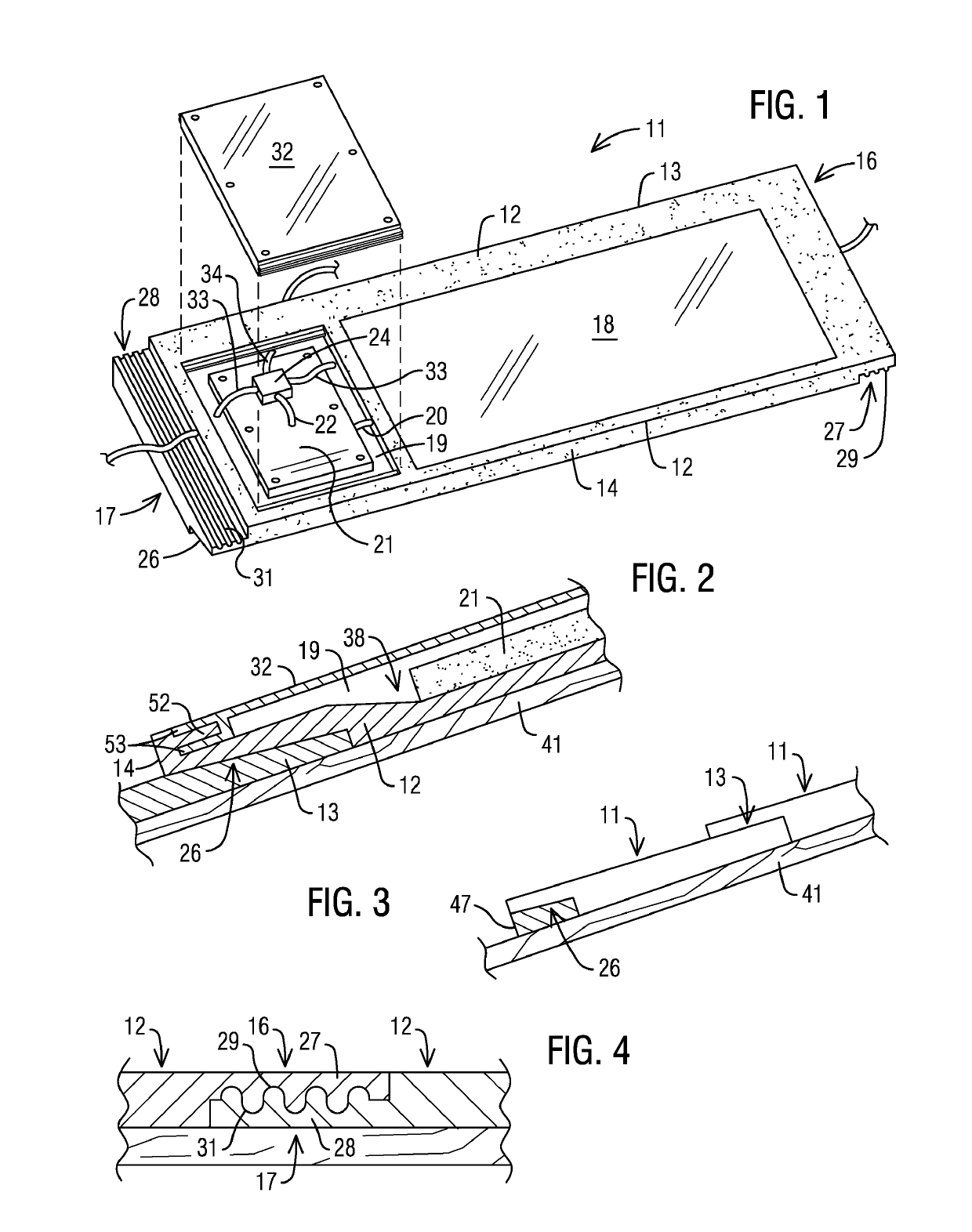
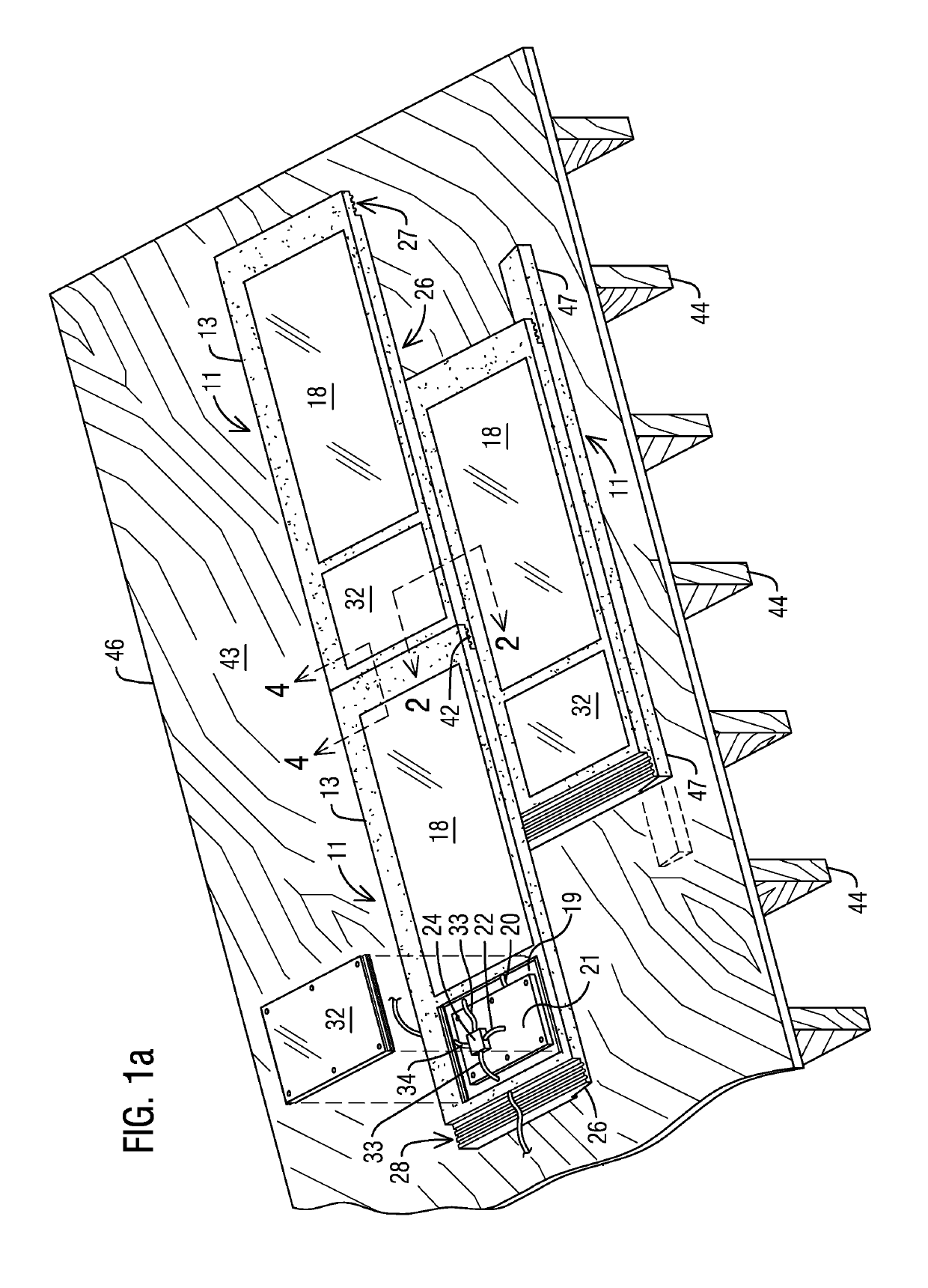
[0019]Referring now in more detail to the drawing figures, wherein like reference numerals, where appropriate, indicate like parts throughout the several views, FIG. 1 illustrates one embodiment of a single solar module 11 of a roof integrated solar panel system according to the invention. The module 11 of this embodiment comprises a frame 12 that can be made of any appropriate material such as, for instance, molded or extruded plastic, aluminum, a polymer composite material, or other material resistant to sun and the weather. The frame has a rear edge portion 13, a front edge portion 14, a right end portion 16, and a left end portion 17. A photovoltaic panel 18 is mounted to or recessed in the top surface of the frame for exposure to sunlight. The photovoltaic panel 18 may conventionally comprise an array of solar cells electrically connected together to form the panel or may comprise any type of photovoltaic technology capable of converting solar energy to electrical energy. The p...


PUM


Abstract

A roof integrated solar power system includes a plurality of solar modules. Each solar module carries a photovoltaic or solar panel with solar cells. Edge regions of the solar module are disposed to the sides of the solar panel and are devoid of solar cells. An electrical component such as a junction box or micro-inverter, or DC optimizer is mounted on top of the solar module within at least one of the edge regions. Cabling for interconnecting the electrical component to electrical components of others of the plurality of solar modules also is located within the side regions. In one embodiment, the electrical component and cabling is disposed within a recess within a side region and covered by a flat access panel. In another embodiment, the electrical component and cabling is located atop the side region and is covered by an access panel in the form of a protective cover strip. The solar modules are installable on a roof in aligned or staggered courses to form the solar power system, and with the installed courses of modules together forming a water barrier protecting the roof.

Description

RELATED APPLICATIONS[0001]This is a continuation-in-part of U.S. patent application Ser. No. 14 / 044,196 filed on Oct. 2, 2013 and entitled Roof Integrated Solar Panel System with Side Mounted Micro Inverters, which claims the benefit of U.S. Provisional Patent Application No. 61 / 708,822, filed on 2 Oct. 2012, and entitled “Roof Integrated Solar Panel System with Side Mounted Micro Inverters.” The disclosures of these prior applications are hereby incorporated by reference in their entireties.TECHNICAL FIELD[0002]This disclosure relates generally to photovoltaic energy production and more specifically to solar panels and associated solar power systems configured to be mounted on the roof of a building for producing electrical energy when exposed to sunlight.BACKGROUND[0003]Collecting energy directly from the sun has drawn more and more interest in the past several years as people and industries turn to more sustainable forms of energy production. One way to collect energy from the su...

Claims


Application Information

Patent Timeline
IPC IPC(8): H02S20/23H02S40/32H01L31/042H01L31/02
CPCH02S20/23H02S40/32H01L31/042H01L31/02008H02S30/00H02S40/34H02S40/36F24S2025/022F24S2025/6007F24S2020/13F24S25/40Y02B10/20Y02E10/50Y02E10/47Y02B10/10
Inventor RODRIGUES, TOMMY F.RAILKAR, SUDHIRBOSS, DANIEL E.GENNRICH, DAVID J.BOUDREAU, CORYNETT, DANIEL R.KALLSEN, KENT J.
Owner BMIC LLC
Learn More