Cartridge
a technology of cartridge and slit, applied in the field of cartridge, can solve the problems of liquid likely to remain and discharge failure, and achieve the effect of avoiding slit and avoiding sli
- Summary
- Abstract
- Description
- Claims
- Application Information
AI Technical Summary
Benefits of technology
Problems solved by technology
Method used
Image
Examples
first embodiment
A. First Embodiment
[0042]A1. Configuration of Liquid Ejection System
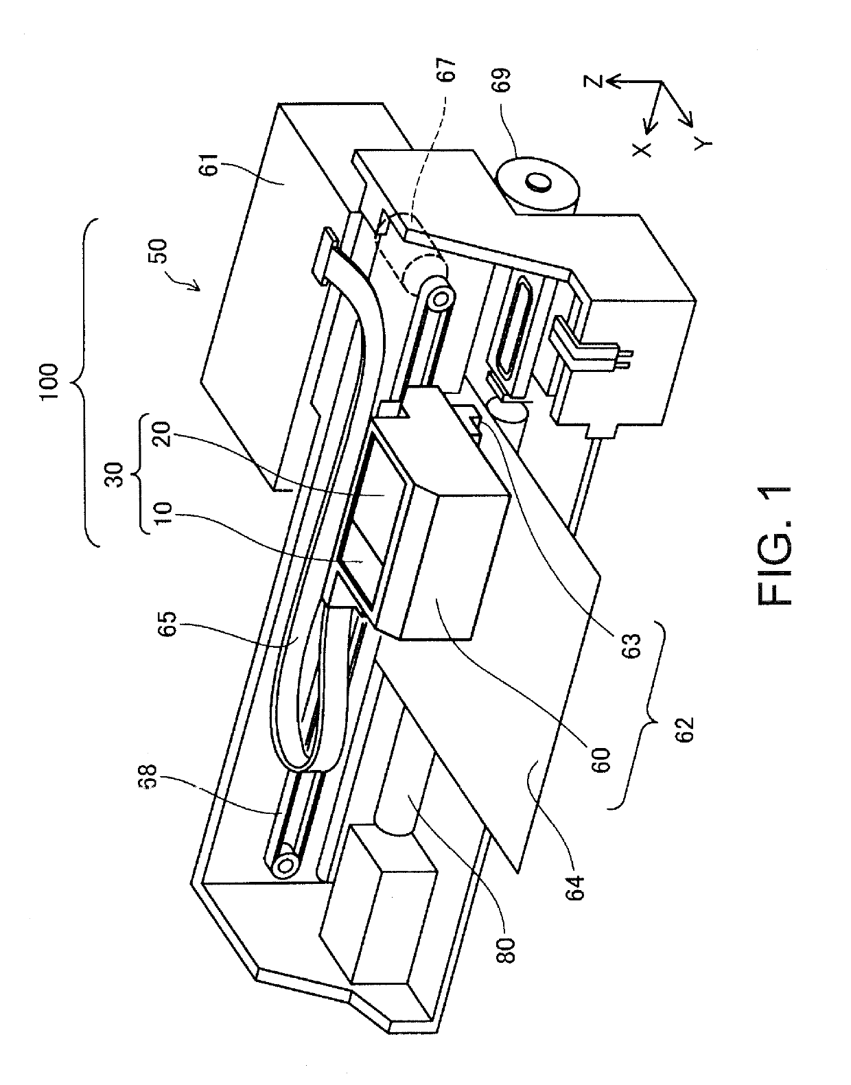
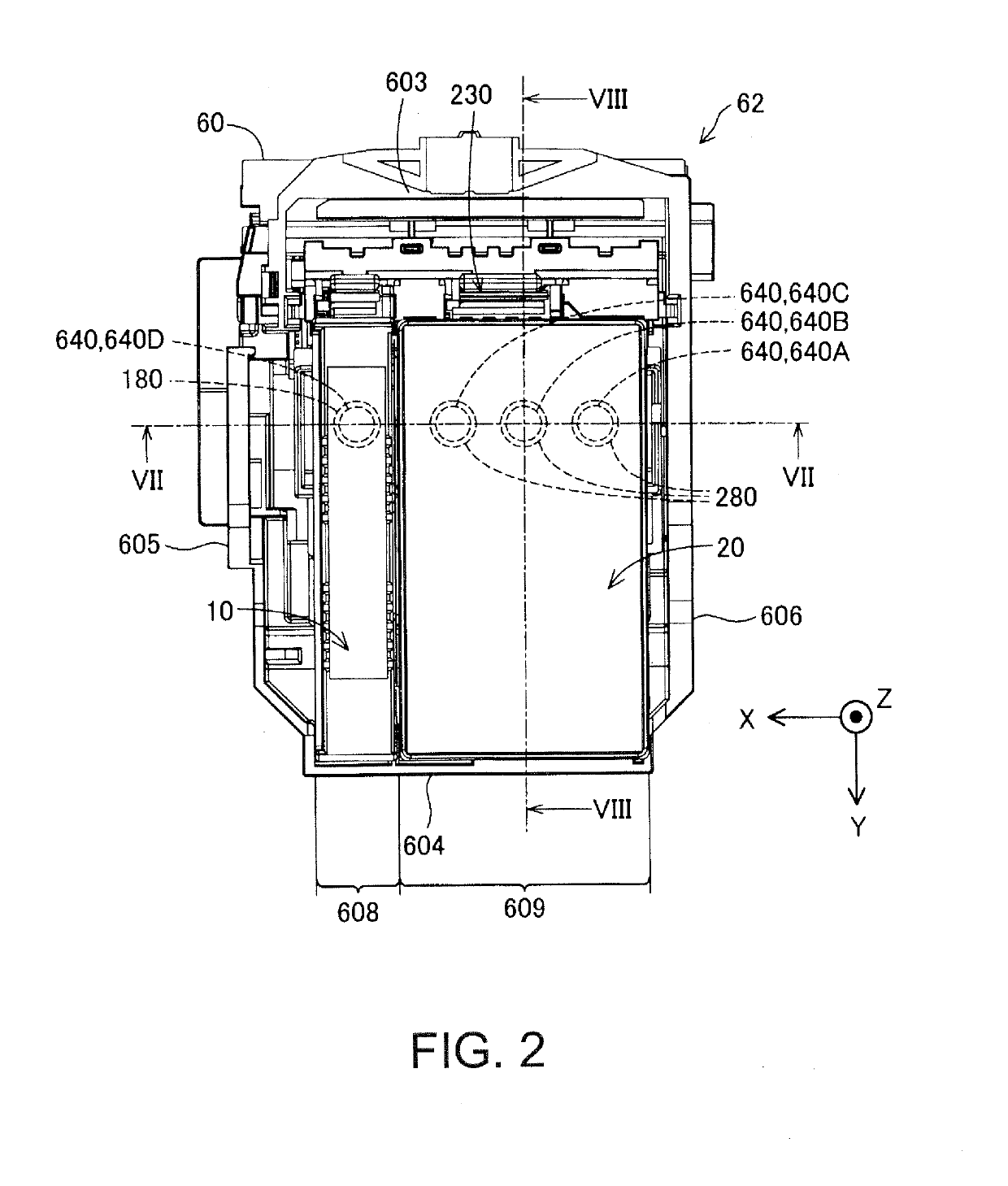
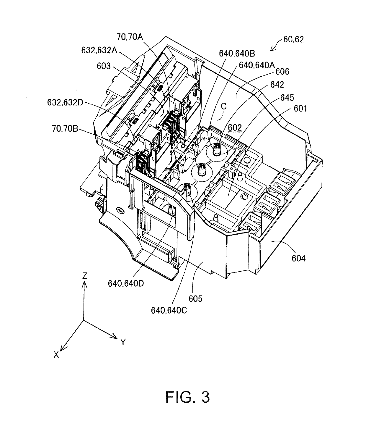
[0043]FIG. 1 is a perspective view illustrating a configuration of a liquid ejection system 100. In FIG. 1, X, Y, and Z axes that are orthogonal to each other are shown. The X, Y, and Z axes in FIG. 1 correspond to the X, Y, and Z axes in the other diagrams. The X, Y, and Z axes are added, as necessary, to diagrams that will be shown in the following. A direction along the X axis is an X direction, a direction along the Y axis is a Y direction, and a direction along the Z axis is a Z direction. Also, one direction in the X direction is a +X direction, and the other direction in the X direction is a −X direction. Also, one direction in the Y direction is a +Y direction, and the other direction in the Y direction is a −Y direction. Also, one direction in the Z direction is a +Z direction, and the other direction in the Z direction is a −Z direction. In a state in which the liquid ejection system 100 is installed on an...
second embodiment
B. Second Embodiment
[0132]FIG. 22 is a cross-sectional view of a cartridge 20b in a second embodiment. FIG. 23 is a perspective view of the cartridge 20b shown in FIG. 22. In the above-described first embodiment, the length of the filter 210 provided in the cartridge 20 is 50% or more of the length of the liquid absorber 299 in the Y direction. In contrast, in the present embodiment, the size of a filter 210b is smaller than 50% of the length of the liquid absorber 299. Also, a bubble trap chamber 212b has a substantially rectangular parallelepiped shape, and liquid guidance passages 231b are formed in inner faces of the bubble trap chamber 212b on the +Y direction side and on the −Y direction side so as to extend in the vertical direction. According to this second embodiment as well, ink inside the bubble trap chamber 212b is allowed to flow smoothly to the liquid supply unit 280.
third embodiment
C. Third Embodiment
[0133]FIG. 24 is a cross-sectional view of a cartridge 20c in a third embodiment. FIG. 25 is a perspective view of the cartridge 20c shown in FIG. 24. In the above-described second embodiment, the length of the filter 210b is smaller than 50% of the length of the liquid absorber 299 in the Y direction. In contrast, in the present embodiment, the length of a filter 210c is 50% or more of the length of the liquid absorber 299, similarly to the first embodiment. Note that, in the present embodiment, unlike the first embodiment, a bottom face 213c of a bubble trap chamber 212c is not inclined toward the liquid supply unit 280, but is flat, and is oriented downward in the vertical direction in the vicinity of the liquid supply unit 280. Also, in the present embodiment, a liquid guidance passage 231c is formed in the horizontal direction in the bottom face 213c of the bubble trap chamber 212c, and is oriented downward in the vertical direction in the vicinity of the bub...
PUM
 Abstract
Description
Claims
Application Information
 - R&D
- Intellectual Property
- Life Sciences
- Materials
- Tech Scout
- Unparalleled Data Quality
- Higher Quality Content
- 60% Fewer Hallucinations
Browse by: Latest US Patents, China's latest patents, Technical Efficacy Thesaurus, Application Domain, Technology Topic, Popular Technical Reports.
© 2025 PatSnap. All rights reserved.Legal|Privacy policy|Modern Slavery Act Transparency Statement|Sitemap|About US| Contact US: help@patsnap.com


